Atomic time signal transmission system and method

A signal transmission system, transmission system technology, applied in the transmission system, digital transmission system, optical fiber transmission, etc., can solve the problems of impracticability, low transmission signal accuracy, limited transmission accuracy, and the stability of portable small atomic clocks. Lock the bandwidth limit, improve the transmission accuracy, and solve the effect of signal attenuation

Active Publication Date: 2013-10-30
TSINGHUA UNIV
View PDF0 Cites 0 Cited by
  • Summary
  • Abstract
  • Description
  • Claims
  • Application Information

AI Technical Summary

Problems solved by technology

[0007] (1) Since the accuracy of atomic time signal transmission is directly limited by the stability of the transportable small atomic clock, and the system error introduced by the transportable small atomic clock during the transport process and the altitude of different locations, the accuracy of the transmitted signal is low.
[0008] (2) The method of transporting the clock must be compared with the clock in A and A, and then transported to B, and compared with the clock in B
Therefore, it is impossible to realize the simultaneous measurement comparison between A and B, resulting in the inability to perform real-time continuous measurement comparison
[0009] (3) The transfer clock method must use the same transfer clock as the atomic time signal transmission medium, so it is impossible to perform time-frequency transfer comparison between multiple places at the same time, that is, it is impossible to perform multi-point synchronization comparison at the same time
That is to say, the actual use of the satellite transfer comparison method is limited by the satellite coverage, so it cannot be well applied to the atomic time signal transfer of ultra-long baselines
[0012] As mentioned above, the existing clock transport method uses a miniaturized high-precision atomic clock as the transmission medium of the atomic time signal, and the existing satellite transmission comparison method uses artificial satellites as the transmission medium of the atomic time signal. These transmission mediums and their transmission There are more or less flaws in the method

Method used


Image

  • Atomic time signal transmission system and method
  • Atomic time signal transmission system and method
  • Atomic time signal transmission system and method

Examples


Embodiment Construction

[0030] In order to make the object, technical solution and advantages of the present invention clearer, the present invention will be further described in detail below in combination with specific embodiments and with reference to the accompanying drawings.

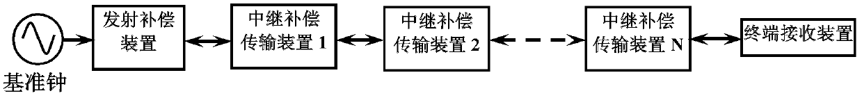
[0031] figure 2 A schematic structural diagram of the atomic time signal transmission system of the present invention is shown.

[0032] Such as figure 2 As shown, the atomic time signal transmission system of the present invention includes: an emission compensation device for modulating the atomic time signal to be transmitted onto an optical signal for transmission through an optical fiber, and compensating for the Phase noise; multiple relay compensation transmission devices are used to further compensate the phase noise introduced when the atomic time signal is transmitted in the optical fiber link. Wherein, the atomic time signal modulated on the optical signal is transmitted between the emission compensation dev...


PUM


Abstract

The invention provides an atomic time signal transmission system and method. In the system, an emitting compensation device at an emission end is used to modulate atomic time signals to be transmitted onto optical signals for transmission by optical fibers and compensate for phase noise introduced by transmitting the atomic time signals in optical fiber links; and a plurality of serially-connected relay compensation transmission devices in each relay end are utilized to further compensate for the phase noise introduced by transmitting the atomic time signals in the optical fiber links, thus locking phases of the atomic time signals transmitted to the far ends at the phase of a reference clock at the emission end. The technical scheme is used for solving the problems of the locking bandwidth limitation and signal attenuation of an over-long base-line atomic time signal transmission loop and improving the transmission distance and transmission accuracy of the atomic time signals greatly.

Description

technical field [0001] The invention relates to a transmission system and a transmission method of an atomic time signal. In particular, it relates to a system and method for realizing ultra-long baseline (distance) atomic time signal transmission through optical fiber. Background technique [0002] At present, there are three main directions in the research and application of time-frequency systems. One is the preparation of the time frequency source, which is used to provide the time reference. The second is the transmission system of time and frequency. With a good reference source, it is necessary to accurately release the time and frequency. Therefore, the quality of the time-frequency transmission system directly determines the quality of the time-frequency signal received by the user terminal. This problem is especially important in ultra-long-distance time-frequency signal transmission. The third is the reception of time-frequency signals. At present, the technol...

Claims


Application Information

Patent Timeline
Patent Type & Authority Patents(China)
IPC IPC(8): H04L7/00H04B10/25
Inventor 王力军李天初王波高超
Owner TSINGHUA UNIV
Why Eureka
Try Eureka