
Shrinkage fit connecting method of worm-gear and leadscrew nut for electric cylinder

A technology of screw nut and connection method, which is applied in the direction of shrinkage connection, connection components, metal processing, etc., can solve the problems of decreased positioning accuracy, different application fields, and different application objects, so as to improve transmission accuracy, reduce processing procedures, and save energy. material effect

Inactive Publication Date: 2009-06-24
SHANGHAI JIAO TONG UNIV
View PDF1 Cites 5 Cited by
  • Summary
  • Abstract
  • Description
  • Claims
  • Application Information

AI Technical Summary

Problems solved by technology

The disadvantage of using a key connection is that there is a gap between the key and the keyway, which causes a relative displacement between the worm wheel and the screw nut. For the ball screw transmission device that requires high positioning accuracy, such relative displacement will affect the transmission accuracy. , in addition, the keyway will produce plastic deformation after working for a long time, resulting in a further decline in positioning accuracy
Although it mentions the red sleeve method, it has two obvious differences from this invention; one: the application field is different, the method is applied to large-scale equipment, and cannot be applied to the electric cylinder field; The red sleeve method applied to the connection between the main shaft and the rotor, not for the connection between the turbine and the screw nut

Method used


Image

  • Shrinkage fit connecting method of worm-gear and leadscrew nut for electric cylinder
  • Shrinkage fit connecting method of worm-gear and leadscrew nut for electric cylinder

Examples


Embodiment Construction

[0015] The embodiments of the present invention are described in detail below in conjunction with the accompanying drawings: this embodiment is implemented on the premise of the technical solution of the present invention, and detailed implementation methods and specific operating procedures are provided, but the protection scope of the present invention is not limited to the following the described embodiment.

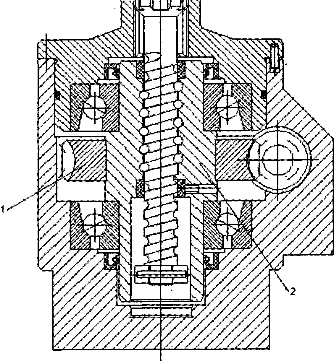
[0016] like figure 1 Shown is the general drawing of the electric cylinder using the red sleeve connection method. The marked ones in the figure are the worm gear 1 and the lead screw nut 2, and the connection method of the worm gear 1 and the lead screw nut 2 is shown in the figure.

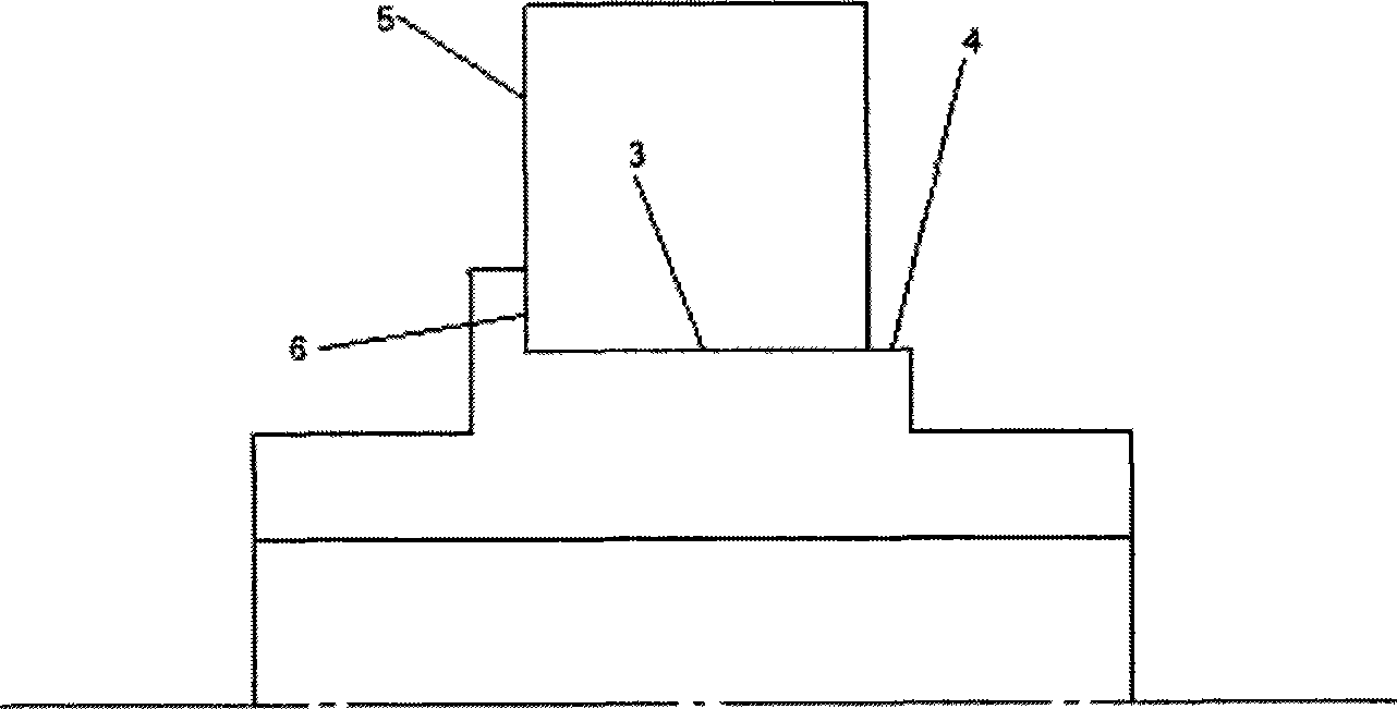
[0017] like figure 2 As shown in the electric cylinder, use the red sleeve connection to connect the worm wheel with the lead screw nut. In the present embodiment, the material of the worm wheel 1 is brass, the outer diameter of the worm wheel is 130cm, and the diameter of the inner...


PUM

PropertyMeasurementUnit
diameteraaaaaaaaaa
diameteraaaaaaaaaa
diameteraaaaaaaaaa

Abstract

The invention relates to a method for connecting a worm wheel of an electric cylinder and a feed screw nut through shrinkage fit in the technical field of mechanical engineering. The method adopts shrinkage fit for connection; the worm wheel in the electric cylinder is directly and fixedly connected with the feed screw nut: step one, a copper worm wheel is put into a resistance furnace, and the temperature of the resistance furnace is set to between 190 and 210 DEG C; step two, a temperature measuring sensor is put on the copper worm wheel for measuring the temperature of the copper worm wheel, and when the temperature of the copper worm wheel rises between 190 and 210 DEG C, the the inside diameter of a copper worm wheel hole is expanded to reach requirement of shrinkage fit; step three, the worm wheel is sleeved with the feed screw nut, and in the sleeve process, the clearance amount between the feed screw nut and the worm wheel is kept even; and step four, when the worm wheel enters a setting position, the power supply of the resistance furnace is closed so as to cool and position the worm wheel and the feed screw nut. Compared with the prior bond connection and bolt connection, the shrinkage fit connection can improve transferring precision of the electric cylinder, save materials, reduce the machining procedures, increase the transferred torsion and improve performance of the electric cylinder.

Description

technical field [0001] The invention relates to a method for connecting transmission parts in the technical field of mechanical engineering, in particular to a method for connecting a worm wheel for an electric cylinder and a screw nut red sleeve. Background technique [0002] Many electric cylinders use worm gear reducers to achieve deceleration and increase torque. There are two connection methods between the worm gear and the lead screw nut of the existing electric cylinder: key connection and screw connection. The disadvantage of using a key connection is that there is a gap between the key and the keyway, which causes a relative displacement between the worm wheel and the screw nut. For the ball screw transmission device that requires high positioning accuracy, such a relative displacement will affect the transmission accuracy. , In addition, the keyway will produce plastic deformation after working for a long time, resulting in a further decline in positioning accuracy...

Claims


Application Information

Patent Timeline
Patent Type & Authority Applications(China)
IPC IPC(8): B23P11/02F16B4/00
Inventor 叶骞金惠良王旭永吴琼冯正进
Owner SHANGHAI JIAO TONG UNIV
Learn More