Blade pitch control in a wind turbine installation

A pitch control, wind turbine technology, applied in the control of wind turbines, mechanical equipment, engine control, etc., can solve problems such as slow blade pitch controllers

Active Publication Date: 2012-01-04
HYWIND AS
View PDF4 Cites 9 Cited by
  • Summary
  • Abstract
  • Description
  • Claims
  • Application Information

AI Technical Summary

Problems solved by technology

[0098] However, if tuned in this way image 3 would result in a very slow blade pitch controller that would not react to changes in wind speed with a period of less than 30 seconds (i.e., a frequency greater than 0.03 Hz)
This can lead to unacceptable performance in relation to key wind turbine parameters such as variations in produced power, shaft torque, rotor speed, rotor thrust, etc.

Method used


Image

  • Blade pitch control in a wind turbine installation
  • Blade pitch control in a wind turbine installation
  • Blade pitch control in a wind turbine installation

Examples


Embodiment Construction

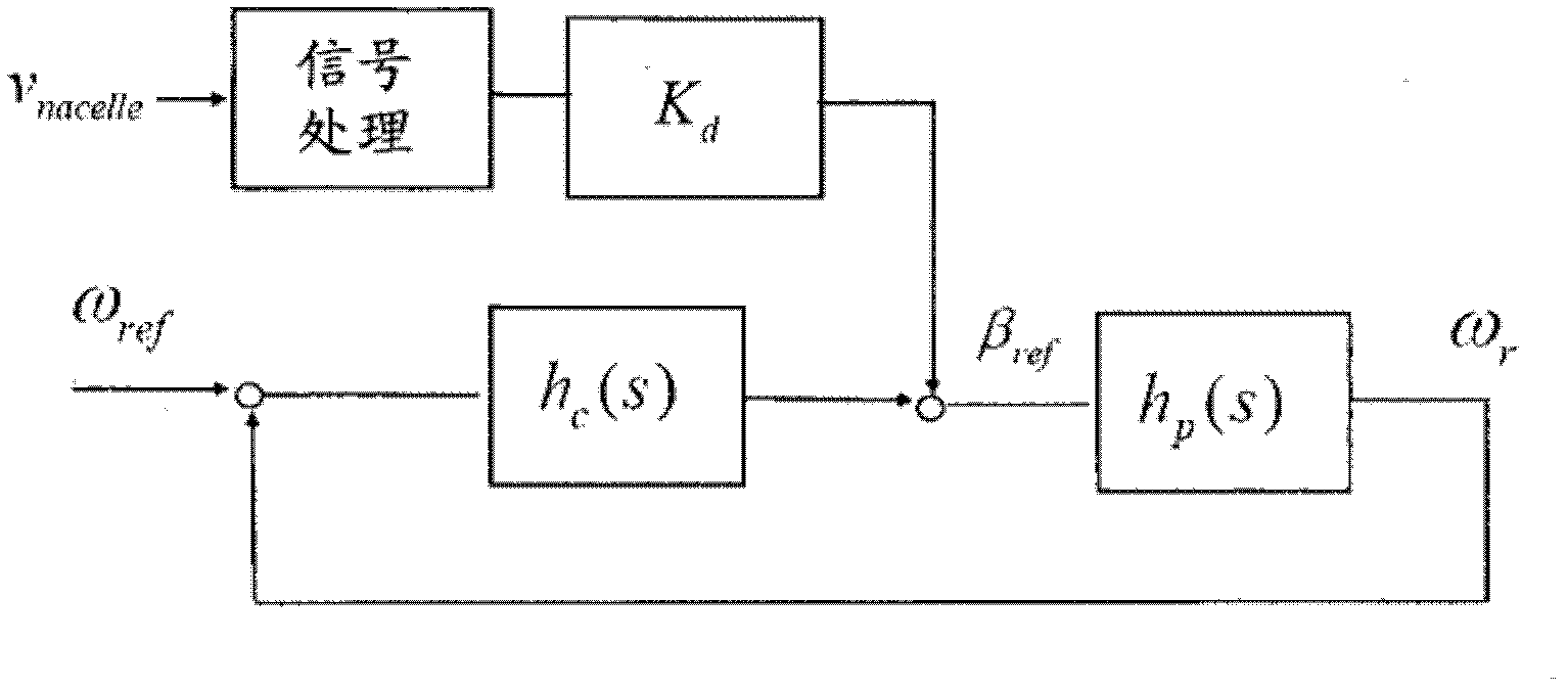
[0138] Figure 4 A schematic diagram of a blade pitch control system with active damping for a floating wind turbine installation is shown.

[0139] Illustration of a blade pitch control system including vibration control for active damping of bending vibrations in a fixed foundation wind turbine image 3 compared to, Figure 4 The shown blade pitch control system for a floating wind turbine uses the transfer function h twice c (s).

[0140] Figure 4 Rotor angular frequency ω in r Can be expressed as:

[0141] ω r ( s ) = h 0 ( s ) 1 + h 0 ( s ) ω ref ...


PUM


Abstract

The present invention relates to a blade pitch controller for a floating wind turbine structure, wherein the floating wind turbine structure comprises a support structure supporting a rotor having a plurality of blades. The controller comprises standard blade pitch control means and active damping means. The standard blade pitch control means is arranged to control a blade pitch using a transfer function between a rotor speed error and the blade pitch. The active damping means is arranged to further control the blade pitch on the basis of a speed of a point on the wind turbine structure by converting the speed of a point on the wind turbine structure into a rotor speed error and using the same transfer function that is used in the standard blade pitch control means to convert the rotor speed error into a correction to the blade pitch.

Description

technical field [0001] The invention relates to the field of rotor blade pitch control for wind turbine installations. More specifically, the present invention relates to rotor blade pitch control for floating wind turbine installations. Background technique [0002] Wind turbine installations are usually formed by a support structure comprising an elongated tower, and a nacelle and a rotor attached to the upper end of the support structure. The generator and its associated electronics are usually located in the nacelle. [0003] Fixed foundation wind turbines secured to the land or sea bed are well accepted. [0004] However, the development of floating wind turbines is expected recently, and various structures have been proposed. An example is wind turbine installations where conventional wind turbine structures are mounted on floating foundations such as platforms or raft-like structures. Another solution is a "spar buoy" type structure. The structure is formed by an...

Claims


Application Information

Patent Timeline
Patent Type & Authority Applications(China)
IPC IPC(8): F03D7/02F03D7/04
CPCF03D7/0224Y02E10/723F05B2270/101F03D7/0276F05B2270/304F05B2260/96F05B2240/93F03D7/043F03D7/0296F05B2270/327F03D13/25Y02E10/727Y02E10/72F03D13/20F03D7/022F03D7/04F05B2270/328
Inventor B·斯科雷F·G·尼尔森
Owner HYWIND AS
Why Eureka
Try Eureka