Electrochemical energy storage device

A technology of electric energy storage device and storage unit, which is applied to electrochemical generators, battery/fuel cell control devices, circuits, etc., to achieve the effect of reducing shaking and avoiding slipping

Inactive Publication Date: 2012-01-04
LI TEC BATTERY
View PDF15 Cites 33 Cited by
  • Summary
  • Abstract
  • Description
  • Claims
  • Application Information

AI Technical Summary

Problems solved by technology

Such an arrangement is no longer removable

Method used


Image

  • Electrochemical energy storage device
  • Electrochemical energy storage device
  • Electrochemical energy storage device

Examples


Embodiment Construction

[0121] More specific embodiments and more possible subtle changes will be described below. Generally speaking, the same structural elements are used in different embodiments, and the same or corresponding reference numerals are used. Under repeated explanations, the explained features that have been linked to an embodiment should be omitted as much as possible. Nevertheless, as long as no additional description is clearly made, or as long as it is not clearly technically meaningless, the features, arrangements, and effects in one embodiment can also be used in another embodiment.

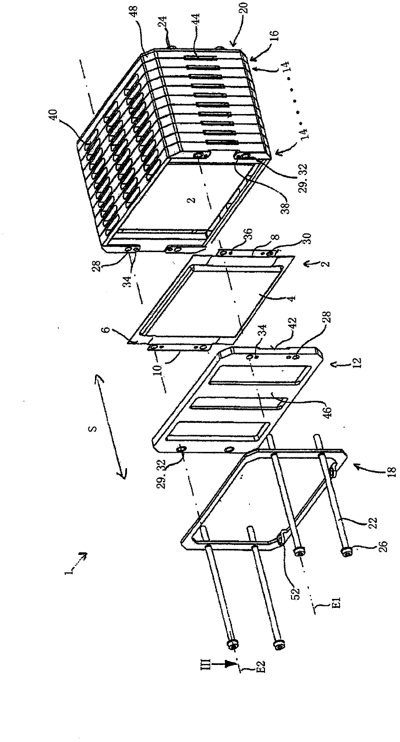
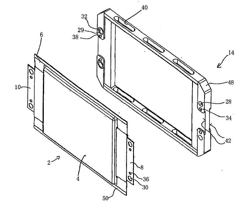
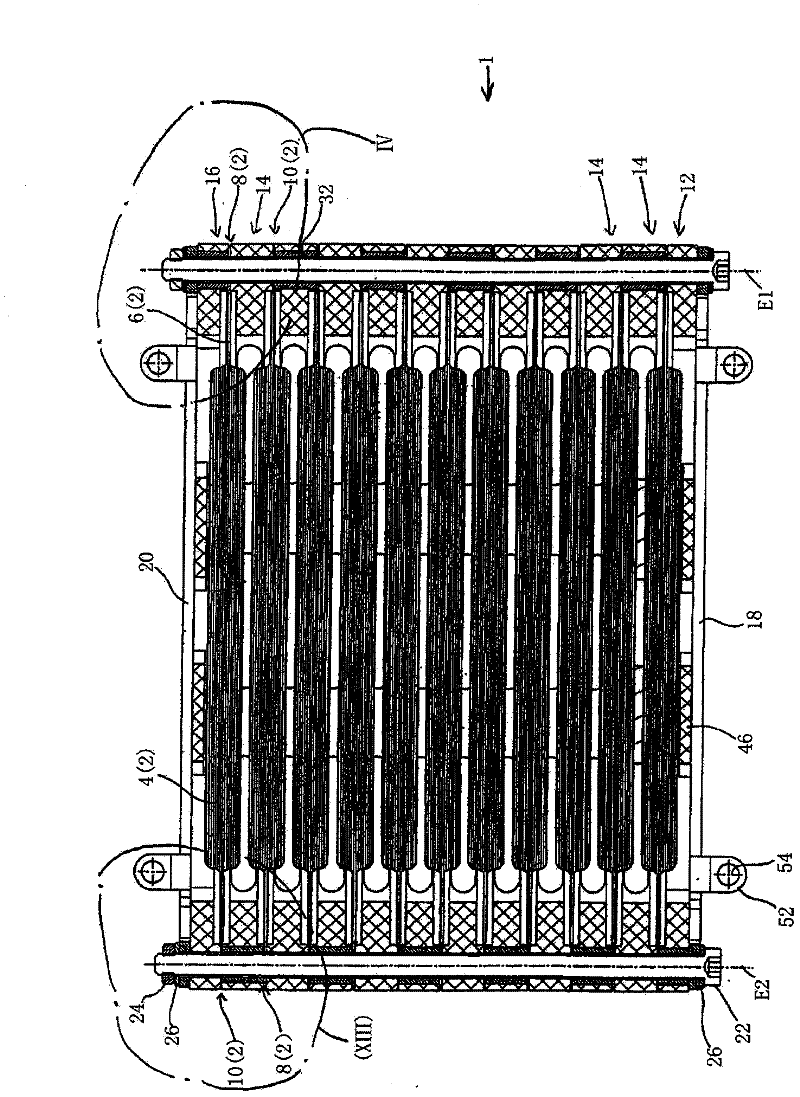
[0122] The first embodiment of the present invention uses Figure 1 to 6 Be explained. among them figure 1 What is shown is a partial exploded view of the battery block corresponding to the first embodiment shown in a perspective perspective; figure 2 Shown is a battery unit and its frame components; image 3 Is a cross-sectional view of the surface defined by the two lines E1 and E2 of the battery ...


PUM


Abstract

A storage device for electric energy according to an aspect of the invention comprises a plurality of flat storage cells (2), wherein a plurality of storage cells (2) are stacked in a stacking direction into a cell block (1) and are held together by a tensioning device (22, 24, 26, 222) between two pressure plates (18, 20), and wherein the storage cells (2) are connected to each other within the cell block (1) in parallel and / or in series. Each storage cell (2) is held in the edge region (6) thereof between two frame elements (12, 14, 16). According to another aspect, each storage cell comprises current conductors (8, 10) in the edge region (6) and electric contacting between current conductors (8, 10) of successive storage cells (2) is carried out via the tensioning device (22, 24, 26, 222) by way of a non-positive fit.

Description

technical field [0001] The invention relates to an electrochemical energy storage device as claimed in claims 1 to 77. Background technique [0002] Batteries (primary energy storage) and accumulators (secondary energy storage) are known to be used for the storage of electrical energy, they are assembled from one or more storage cells in which, when the charging current is switched on, The electrical energy is converted into chemical energy and stored in the electrochemical charging reaction between the cathode and the anode, or in the electrolyte, and therein, when an electrical load is switched on, the chemical energy is converted into electrical energy by an electrochemical discharge reaction. Furthermore, primary energy storage can in principle only be charged once and cleared after discharge, while secondary energy storage allows multiple (from a few hundred to more than 10,000 cycles) charging and discharging. It should also be noted that accumulators, sometimes also ...

Claims


Application Information

Patent Timeline
Patent Type & Authority Applications(China)
IPC IPC(8): H01M2/02H01M2/10H01M2/20H01M2/22H01M2/24H01M2/34H01M10/04H01M10/50H01M10/02H01M10/42H01M10/052H01M50/178H01M50/211H01M50/503H01M50/517H01M50/522H01M50/528H01M50/529H01M50/548H01M50/557H01M50/562
CPCH01M10/5075H01M2/342B60L11/1879H01M2/0212H01M2/0275H01M10/0481H01M10/052H01M2/22H01M2/204H01M10/5057Y02T10/705H01M2/0217H01M10/5032H01M2/021H01M10/5016H01M10/5055Y02T10/7011H01M2/24H01M10/5079H01M10/425H01M10/0436Y02T10/7005B60L11/1874H01M2/1061H01M10/5063H01M10/5004H01M10/625H01M10/647H01M10/6556H01M10/6569H01M10/6567H01M10/6555H01M10/6561H01M10/613B60L58/26B60L50/64Y02E60/10Y02T10/70H01M50/103H01M50/557H01M50/528H01M50/529H01M50/597Y02P70/50H01M50/522H01M50/562H01M50/517H01M50/178H01M50/503H01M50/211H01M50/548
Inventor 延斯·梅恩斯彻克劳迪娅·布拉塞托尔斯滕·施密特克劳斯-鲁珀特·洪门塔勒
Owner LI TEC BATTERY
Why Eureka
Try Eureka