Discharging batteries
A technology for batteries and battery packs, which is applied in secondary battery charging/discharging, battery circuit devices, charging and maintenance charging/discharging, etc., can solve problems such as low discharge efficiency, increase discharge efficiency, reduce environmental waste, and prolong battery life. effect of life
- Summary
- Abstract
- Description
- Claims
- Application Information
AI Technical Summary
Problems solved by technology
Method used
Image

Examples
Embodiment Construction
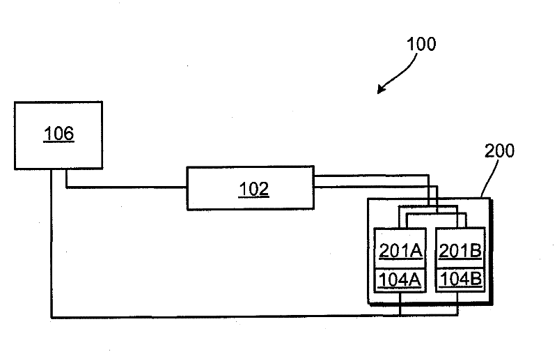
[0023] figure 1 An example of a charging / discharging system 100 is shown, which includes a charging / discharging module 102 , sensor modules 104A, 104B, and a control module 106 , and is connected to a battery pack 200 . Although the battery pack 200 shown includes two batteries 201A, 201B connected in parallel, the system 100 may be connected to a single battery or multiple batteries connected in series, parallel, or some combination thereof. Batteries 211B, 221B can be of common types, depending on the desired application, operating environment, and cost including, for example, sealed lead-acid batteries, Ni-Cad batteries, NiMH batteries, Li-polymer batteries, or Li-ion batteries, or any other suitable battery. Furthermore, the batteries 211B, 221B may be single-cell batteries or multi-cell batteries. For example, in one example, the sealed lead-acid battery 211B, 221B may include a single 1.5 volt cell; in another example, the battery may include a combination of cells, su...
PUM
 Abstract
Description
Claims
Application Information
 - R&D
- Intellectual Property
- Life Sciences
- Materials
- Tech Scout
- Unparalleled Data Quality
- Higher Quality Content
- 60% Fewer Hallucinations
Browse by: Latest US Patents, China's latest patents, Technical Efficacy Thesaurus, Application Domain, Technology Topic, Popular Technical Reports.
© 2025 PatSnap. All rights reserved.Legal|Privacy policy|Modern Slavery Act Transparency Statement|Sitemap|About US| Contact US: help@patsnap.com