
Dehumidifier

A technology for dehumidifiers and heaters, applied in the field of dehumidifiers, can solve the problems of high cost of dehumidification process and inability to realize the utilization of waste heat in the system, so as to achieve the effect of reducing operating costs and realizing the utilization of waste heat

Inactive Publication Date: 2012-01-11
HUBEI ZHONGSHENG WATER SAVING CO LTD
View PDF5 Cites 0 Cited by
  • Summary
  • Abstract
  • Description
  • Claims
  • Application Information

AI Technical Summary

Problems solved by technology

[0003] The present invention mainly solves the technical problems of high dehumidification process cost in the prior art and cannot realize waste heat utilization inside the system; it provides a method that satisfies the basic dehumidification function and realizes waste heat utilization inside the system, A dehumidifier that can flexibly utilize the two-stage dehumidifier of the cold water cooler and the brine cooler during operation to reduce operating costs

Method used


Image

  • Dehumidifier
  • Dehumidifier

Examples


Embodiment

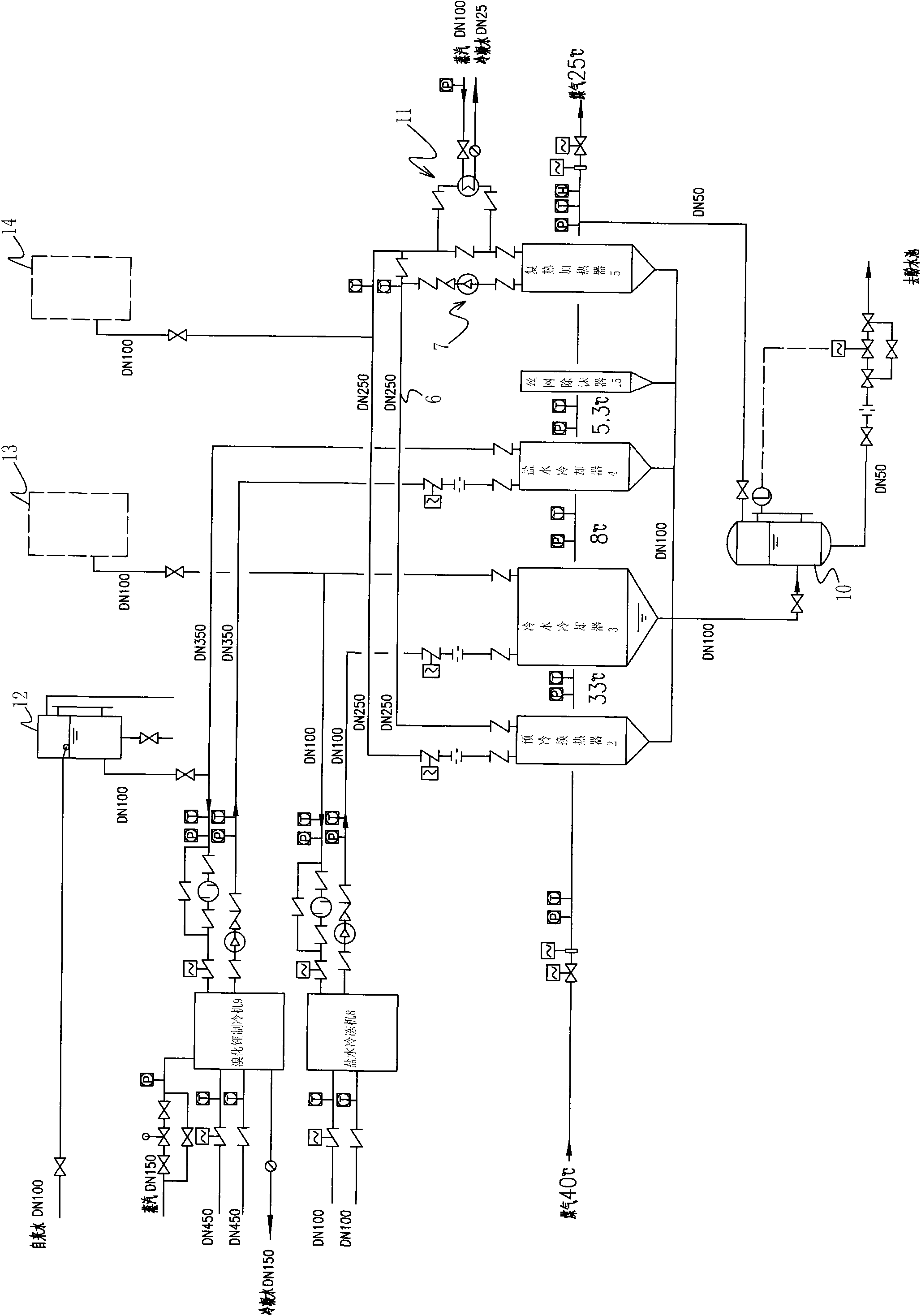
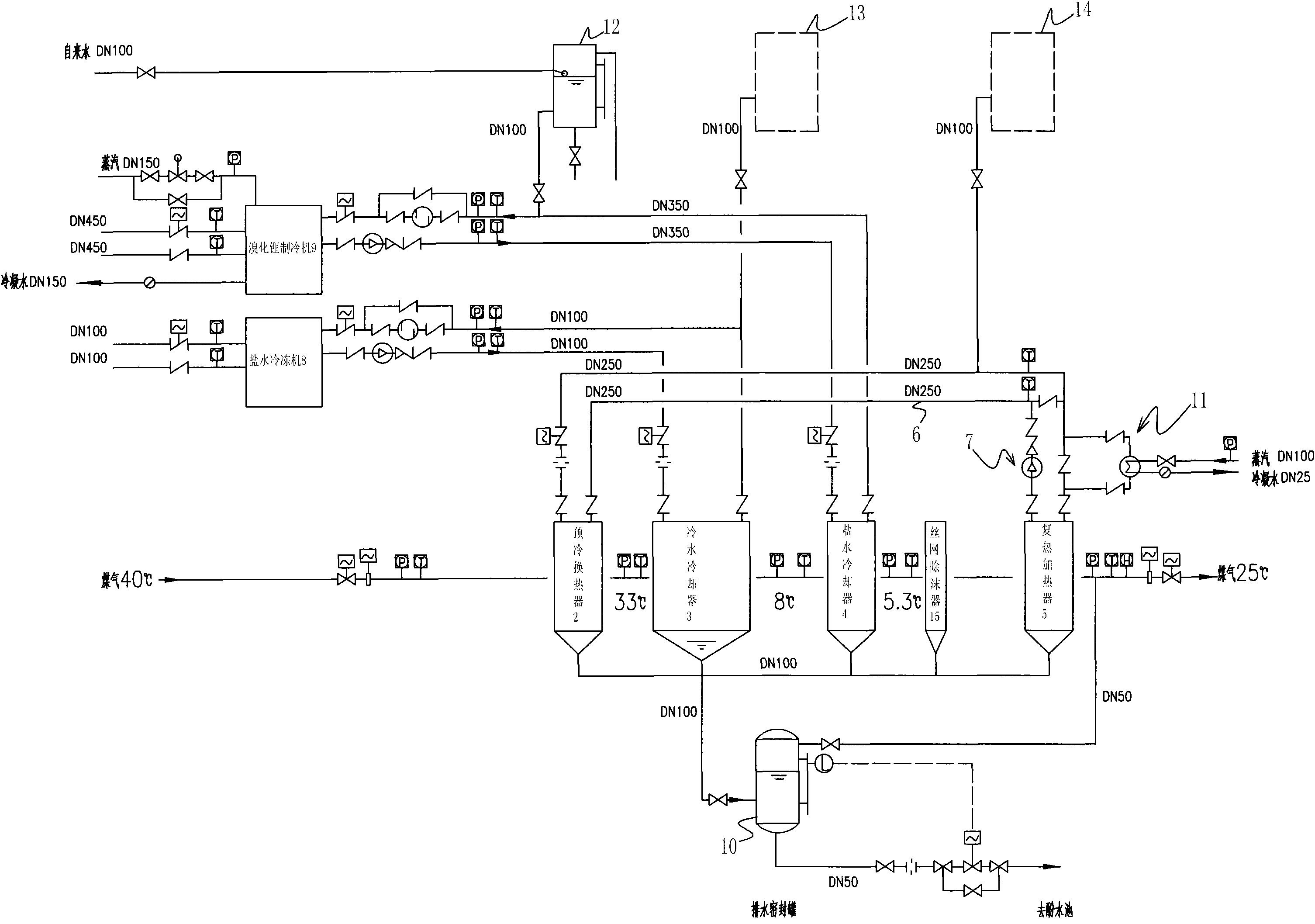
[0020] A dehumidifier comprising a housing and a pre-cooling heat exchanger 2, a cold water cooler 3, a brine cooler 4 and a reheating heater 5 arranged in the housing and sequentially connected, characterized in that the pre-cooling The internal medium of the cold heat exchanger 2 and the reheating heater 5 is connected through a circulation pipe 6, and a self-circulation pump 7 is also arranged on the circulation pipe 6, a brine refrigerator 8 is also connected on the cold water cooler 3, and a brine cooler 4 is also connected A lithium bromide refrigerator 9 is connected, the cold water cooler 3 is also connected with a drainage sealing tank 10, the circulation pipe 6 is also provided with a steam-water heat exchanger 11, and an expansion tank 12 is also arranged between the brine cooler 4 and the lithium bromide refrigerator 9 An expansion tank two 13 is also arranged between the cold water cooler 3 and the brine refrigerator 8, an expansion tank three 14 is also arranged b...


PUM


Abstract

The invention relates to a dehumidifier, in particular to a structure improvement of a dehumidifier capable of recycling a cooled heat source of coal gas. The dehumidifier comprises a shell as well as a pre-cooling heat exchanger (2), a cold water cooler (3), a brine cooler (4) and a recuperative heater (5) which are arranged inside the shell and connected in sequence. The dehumidifier is characterized in that the internal medium of the pre-cooling heat exchanger (2) and the internal medium of the recuperative heater (5) are connected through a recycling pipe (6). Therefore, the dehumidifier provided by the invention has the advantages of satisfying a basic dehumidifying function, realizing residual-heat utilization inside a system and reducing operation cost by flexibly using the two-level dehumidifier comprising the cold water cooler and the brine cooler in operation.

Description

technical field [0001] The invention relates to a dehumidifier, in particular to an improved structure of a dehumidifier capable of recovering gas cooling heat sources. Background technique [0002] At present, many iron and steel enterprises produce a large amount of gas during the blast furnace smelting process. In order to effectively use this energy, most of them use gas turbines as prime movers to drive generators to generate electricity. Before the gas enters the gas turbine, pretreatment such as dust removal, cooling and dehumidification is required to meet the gas quality requirements of the gas turbine. Contents of the invention [0003] The present invention mainly solves the technical problems of high dehumidification process cost in the prior art and cannot realize waste heat utilization inside the system; it provides a method that satisfies the basic dehumidification function and realizes waste heat utilization inside the system, A dehumidifier that flexibly ...

Claims


Application Information

Patent Timeline
Patent Type & Authority Applications(China)
IPC IPC(8): C21B5/06
CPCY02P10/25
Inventor 冯晓强戴月秀马涛肖云飞杨学龙
Owner HUBEI ZHONGSHENG WATER SAVING CO LTD
Learn More