Liquid sample defoamer

A liquid sample and bubble remover technology, which is applied in the preparation of test samples, etc., can solve the problems of large reverse movement resistance of bubbles, large flow resistance of liquid samples, affecting detection, etc., reducing the retention time, facilitating re-sampling, The effect of improving the defoaming effect

Inactive Publication Date: 2012-01-11
FOCUSED PHOTONICS +2
View PDF6 Cites 7 Cited by
  • Summary
  • Abstract
  • Description
  • Claims
  • Application Information

AI Technical Summary

Problems solved by technology

[0007] The position of the injection port cannot be lower than the sampling port, and the vertical distance between the two must be relatively large to have a better defoaming effect, which makes the volume of the defoamer unable to be made smaller;
[0008] 2. The defoaming performance is greatly affected by the defoaming screen
[0009] When the defoaming screen is denser, the resistance to the reverse movement of the bubbles is greater, and the defoaming effect is better; but the denser defoaming screen has relatively greater flow resistance to liquid samples;
[0010] 3. Solid impurities are easy to block the defoaming screen and sampling port, which interrupts the detection
[0011] Since the sampling port is set at the bottom of the tank, some solid impurities in the liquid that are not intercepted by the defoaming wire mesh will be discharged together with the liquid, thereby affecting subsequent detection; at the same time, the solid impurities in the liquid sample are easy to block the defoaming wire The net and sampling port prevent liquid samples from being sampled normally and affect subsequent testing;
[0012] 4. Large dead volume and difficult sample reflux
[0013] The position of the injection port cannot be lower than the sampling port, and in some special applications, it is impossible to realize the backflow of liquid samples from the sampling port; the dead volume of the defoamer is large, and there are problems such as serious hysteresis of the re-sampling system

Method used


Image

  • Liquid sample defoamer
  • Liquid sample defoamer
  • Liquid sample defoamer

Examples


Embodiment 1

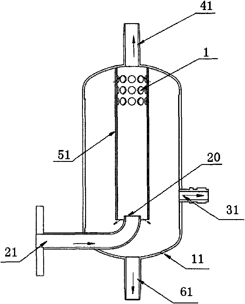
[0041] see figure 2 , a liquid sample defoamer, including a tank 11, a sample tube 21, a sample outlet 31, an exhaust port 41, an air duct 51 and a sewage outlet 61.

[0042] The exhaust port 41 is arranged at the top of the tank body 11 , the sewage outlet 61 is arranged at the bottom of the tank body 11 , and the sample outlet 31 is arranged at the side of the tank body 11 .

[0043] Both ends of the air guide tube 51 are open, and the upper end is connected with the tank body 11 , and the inside of the air guide tube 51 communicates with the exhaust port 41 . The hole 1 is provided in the upper part of the air duct 51 . The lower end of the air duct 51 is suspended.

[0044] One end of the sampling tube 21 is the sampling port 20 , and this end goes deep into the inside of the gas guiding tube 51 from the bottom of the gas guiding tube 51 , so that the liquid sample can directly enter the gas guiding tube 51 through the sampling port 20 of the sampling tube 21 . The pos...

Embodiment 2

[0052] A liquid sample defoamer, which is different from Embodiment 1 in that: one end of the sampling tube passes through the side of the air guide tube and goes deep into the air guide tube.

Embodiment 3

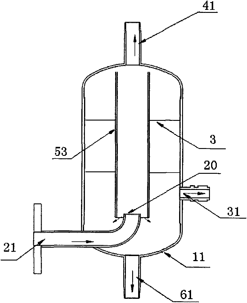
[0054] see image 3 , a liquid sample defoamer, different from Embodiment 1:

[0055] The air guide tube 53 is fixed on the tank body 11 through the fixing frame 3 , and the upper end is kept at a certain distance from the top of the tank body 11 . Bubbles in the liquid sample outside the air guide tube 53 move upward under the action of buoyancy. These bubbles pass through the gap between the air guide tube 53 and the tank body 11 to escape the liquid sample, and then burst and be discharged through the exhaust port 41 .


PUM


Abstract

The invention relates to a liquid sample defoamer. The defoamer comprises a tank body, a sample inlet, a sample outlet and an air outlet, and is characterized in that: an air guiding tube is arranged in the tank body; the inside of the air guiding tube is communicated with the air outlet; the air guiding tube is communicated internally and externally on the upper part and the lower part of the air guiding tube; and a liquid sample passes through the sample inlet to enter the air guiding tube. The defoamer has the advantages of good defoaming effect, small volume, low cost, small dead volume and the like.

Description

technical field [0001] The invention relates to a liquid sample defoamer. Background technique [0002] In the field of liquid analysis, the liquid often contains various solid impurities and bubbles, and when the liquid moves in the pipeline, the movement of the liquid itself and the fluctuation of pressure will also produce bubbles. When the liquid sample reaches the detection area, due to the influence of air bubbles and solid impurities, the measurement results will have large deviations. For example, air bubbles will shift the absorption spectrum of the sample, which will affect the analysis results. [0003] In order to ensure the measurement stability of the liquid detection system, it must be ensured that the liquid sample entering the detection system does not contain air bubbles or solid impurities. This requires the liquid sample to go through a defoaming step and a solid impurity removal step before entering the detection cell. [0004] see figure 1 , a conven...

Claims


Application Information

Patent Timeline
Patent Type & Authority Applications(China)
IPC IPC(8): G01N1/34
Inventor 章松波郑利武张学锋叶华俊陈生龙
Owner FOCUSED PHOTONICS
Why Eureka
Try Eureka