Slanting axial piston pump

A technology of axial piston pump and swash plate, applied in the field of axial piston pump/motor, can solve the problems of increasing the axial load of the drive shaft, reducing the self-priming performance of the pump, and decreasing the volumetric efficiency, so as to increase the rated working pressure , to achieve sealing performance, improve the effect of starting performance

Inactive Publication Date: 2005-12-07
袁训中
View PDF5 Cites 13 Cited by
  • Summary
  • Abstract
  • Description
  • Claims
  • Application Information

AI Technical Summary

Problems solved by technology

However, its small and avoidable flow, pressure pulsation, hydraulic shock and noise, poor self-priming, poor bearing stress, and insufficient lubrication and sealing performance hinder the further improvement of its performance and engineering applications. The specific performance is as follows:
[0003] 1) The working fluid of the slipper hydrostatic bearing of the traditional swash plate pump is provided by the plunger cavity through the throttle hole in the plunger, which reduces the volumetric efficiency of the swash plate pump
At the same time, the static pressure bearing of each plunger shoe bears the supporting function independently, and its supporting area is small, and the effect of centrifugal force makes the sliding shoe tilt, which increases the leakage. Therefore, a larger leakage is required to ensure sufficient supporting force. Volumetric efficiency drops further
The contradiction between the volumetric efficiency and the static pressure bearing capacity hinders the further improvement of pump power and efficiency
[0004] 2) Since the slender hole is difficult to process, in order to ensure the processability, the hole in the plunger is divided into two sections. The hole near the end of the sliding shoe is used as a small throttle hole, and the hole near the end of the flow distribution device is larger and longer. The plunger The ratio of the effective working volume between the inner cavity and the plunger cavity is large, which reduces the self-priming performance of the pump
[0005] 3) Since there is no direct connection between the sliding shoe and the swash plate of the swash plate pump, the plunger is forced to move by the swash plate during the oil pressure stage, but the return of the plunger cannot be guaranteed during the oil suction stage (the plunger protrudes outwards)
[0006] 4) In order to ensure that the rotating cylinder can maintain the seal of the flow distribution device when it is started, a spring is required to compress it, and conventional through-axis pumps, such as Japan's Komatsu (Komatsu) seawater hydraulic pump (see "Hydraulic and Pneumatic" 2000 "Introduction to several medium and high seawater hydraulic pumps" in No. 4 of 2010), the spring is pressed on the transmission shaft through a sleeve, which also increases the axial load of the transmission shaft
[0007] 5) During the flow distribution process of the swash plate pump, because the plunger cavity periodically inputs / outputs the hydraulic medium alternately from the high-pressure area and the low-pressure area, and there is a blind area on the flow distribution device, hydraulic shock, gas pressure, etc. are inevitably generated. erosion and noise
However, processing the groove of the sealing assembly on the plunger makes this solution more difficult to implement because of the hole cavity processed in the plunger

Method used


Image

  • Slanting axial piston pump
  • Slanting axial piston pump
  • Slanting axial piston pump

Examples


Embodiment Construction

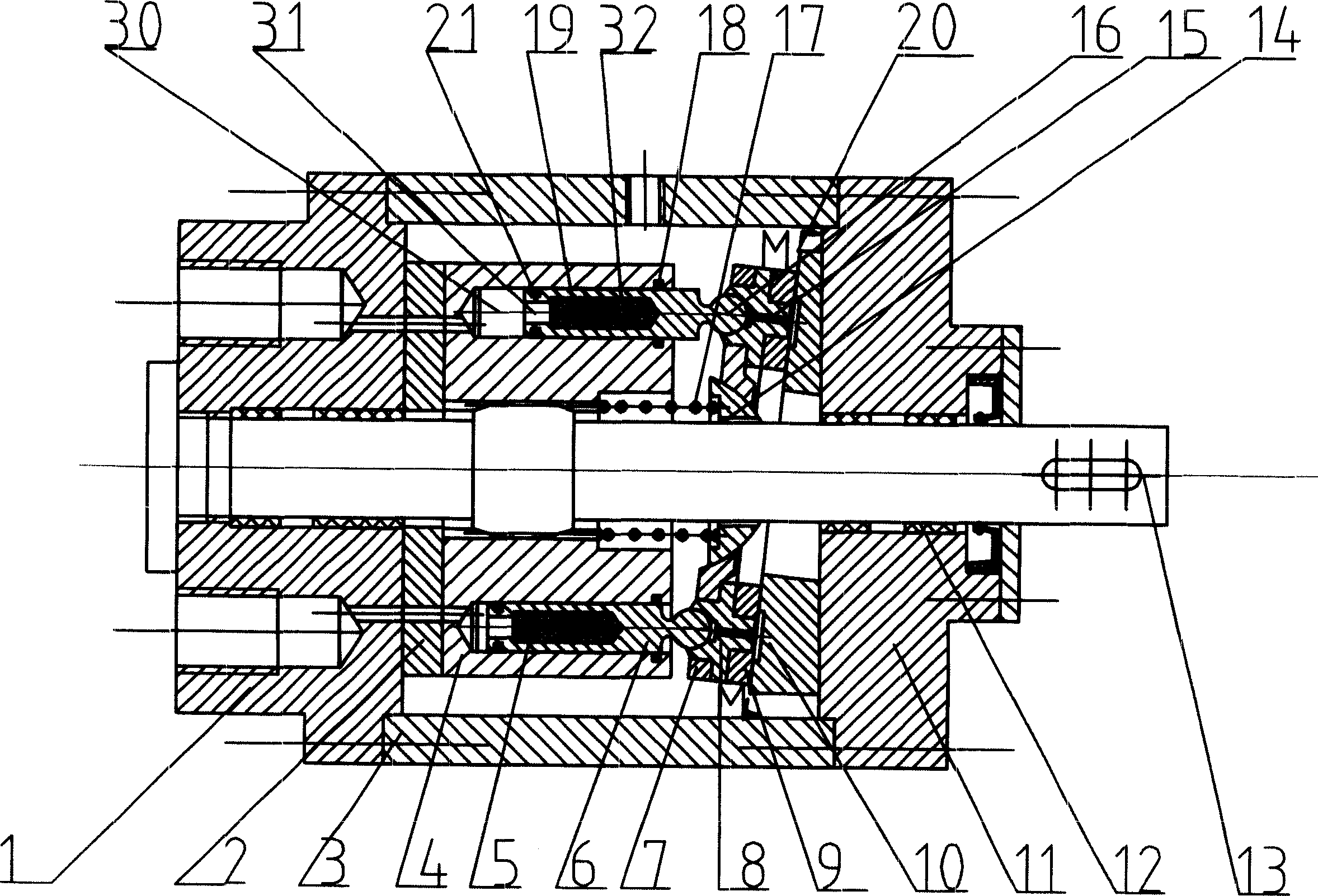
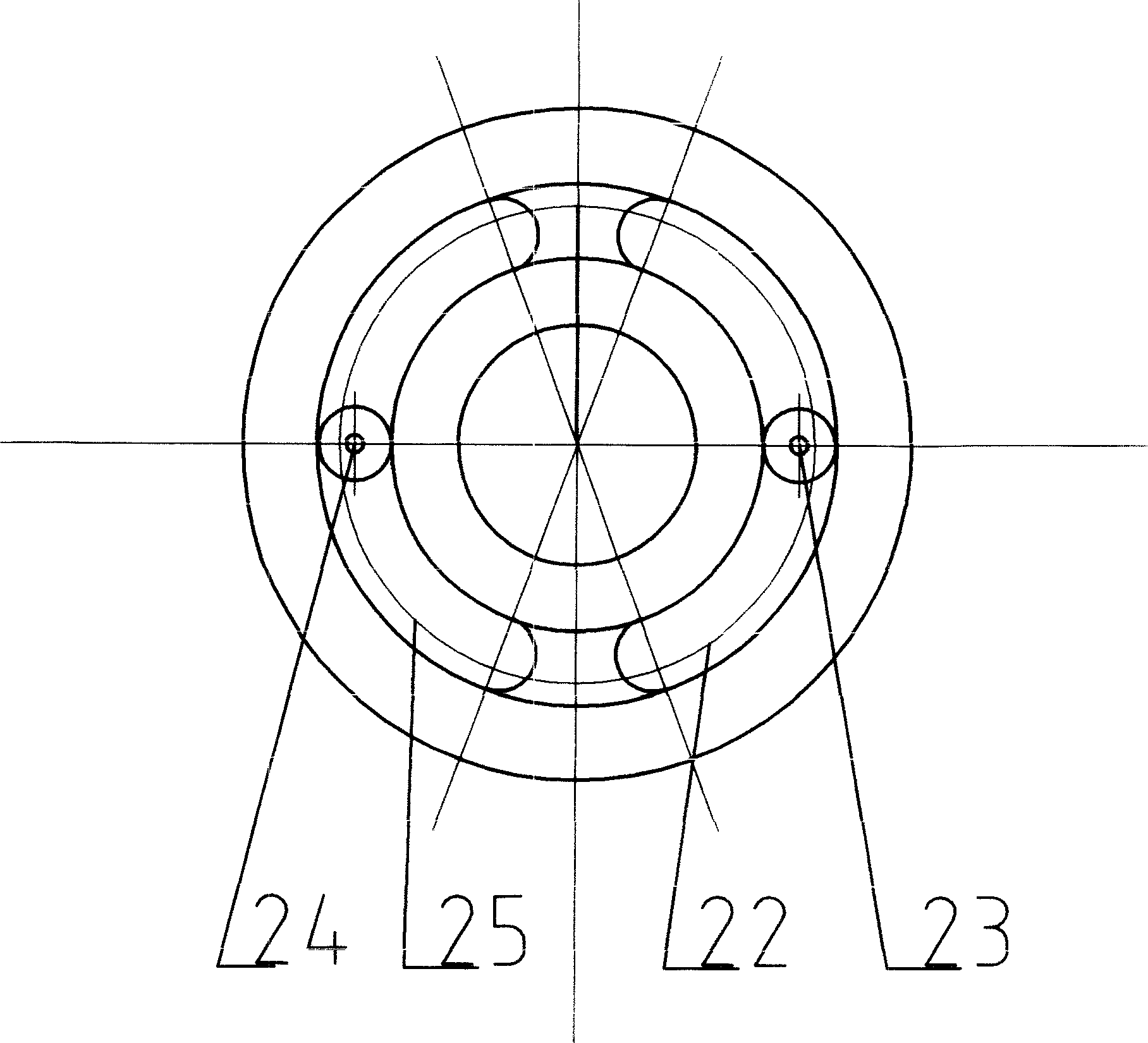
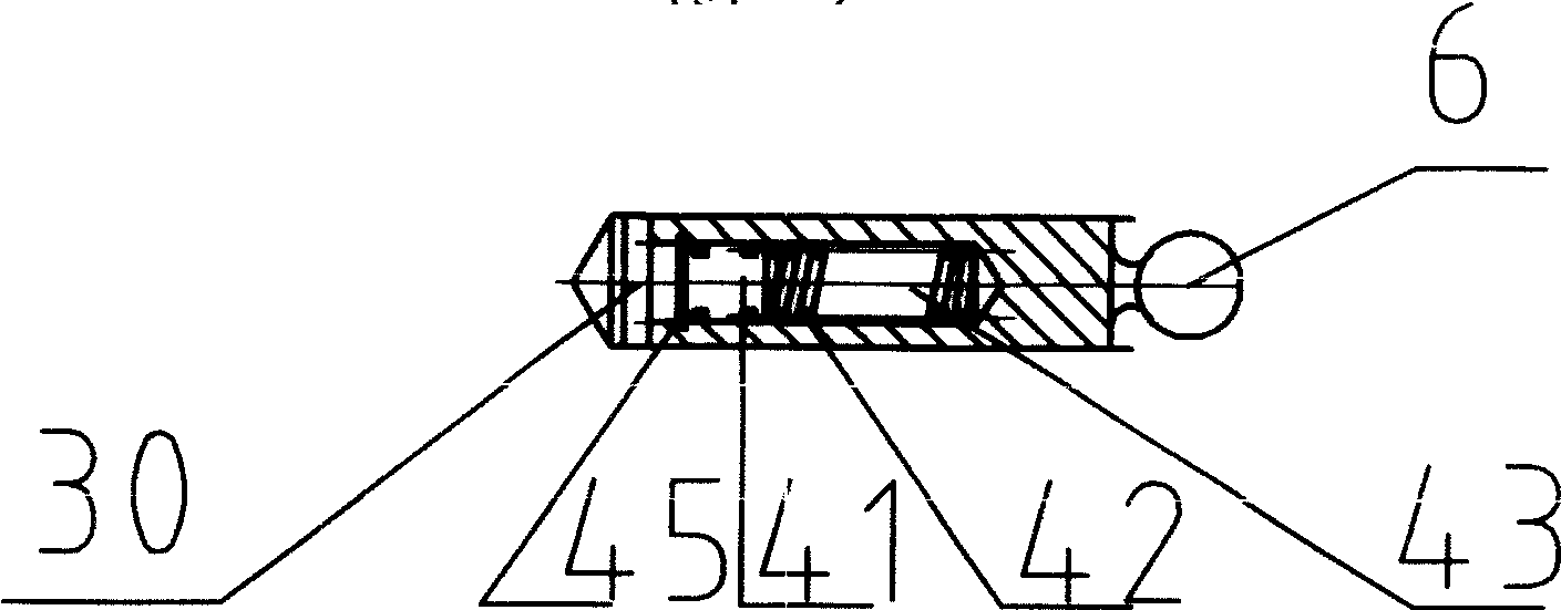
[0051] Such as figure 1 , figure 2 As shown, the patent of the present invention includes a front pump cover 11, a rear pump cover 1, and a pump body 3 connected with the front pump cover 11 and the rear pump cover 1 by bolts; the cylinder body with a plunger cavity 30 parallel to its axis is evenly distributed inside 4. The cylinder 4 can slide axially along the drive shaft 13; the flow distribution device 2 installed between the cylinder 4 and the rear pump cover 1;-one end is ball-hinged with the sliding shoe 8 and the other end is placed in the plunger cavity 30 The plunger 6, the plunger 6 has an inner plunger cavity 19 that communicates with the plunger cavity 30 on the side facing the flow distribution device 2, which is a blind cavity; the plunger inner cavity 19 has a small hole section facing the flow distribution device side 31. There is a large hole section 32 towards the blind end, and polyurethane elastomer is poured into the large hole section as the accumulator 5;...


PUM


Abstract

This invention comprises front pump cover 11, rear pump cover 1, pump 3, cylinder 4, porting device 2, plunger 6 whose one end hinges the sliding boot 8, the other end is in the plunger cavity 30, swash plate 10 whose incidence can be or not be adjusted, static supporting 20 between the swash plate 10 and the sliding boot 8, hold-down spring 15, drive axle bearing and seal assembly 12, and drive axle 13; wherein the plunger 6 has inner cavity 19, a blind hole cavity with accumulator 5; between the sliding boot 8 and the swash plate 10 is a supporting plate 9 which can be rotated. Said invention can absorb the pulsing flow and hydrodynamic shock effectively, and it is especially fit for hydraulic driving pump and motor.

Description

Technical field [0001] The patent of the invention belongs to fluid variable volume machinery, specifically pumps and motors, and particularly relates to an axial piston pump / motor. Background technique [0002] The swash plate axial piston pump (except for the patent of the present invention, all referred to as swash plate pump, the same below) has an important position in various positive displacement pumps due to its advantages of reliable sealing, high working pressure, and large power per unit mass. However, its small and avoidable flow, pressure pulsation, hydraulic shock and noise, poor self-priming, poor bearing force, and insufficient lubrication and sealing performance hinder its further improvement in performance and engineering applications. The specific performance is as follows: [0003] 1) The working fluid of the sliding shoe hydrostatic bearing of the traditional swash plate pump is provided by the plunger cavity through the orifice in the plunger, which reduces ...

Claims


Application Information

Patent Timeline
Patent Type & Authority Applications(China)
IPC IPC(8): F04B49/08
Inventor 袁训中
Owner 袁训中
Why Eureka
Try Eureka