
Covered wire fiber connector

A technology of optical fiber connectors and leather wires, which is applied in the field of leather wire optical fiber connectors, and can solve problems such as unusable, prolonged construction time, and increased loss of link optical signals.

Inactive Publication Date: 2012-01-11
河北恒辉通信设备有限公司
View PDF4 Cites 21 Cited by
  • Summary
  • Abstract
  • Description
  • Claims
  • Application Information

AI Technical Summary

Problems solved by technology

[0003] The method of using the quick connector to directly end may need to be remade to waste labor and prolong the construction time if the fiber cutting end face is not good; after repeated unsuccessful operations, it is likely to cause the quick connector to be scrapped and cannot be used; Professional people are needed to train and learn the assembly and testing of each brand of quick connectors; after the quick connectors are finished, they can only bear a certain degree of tensile force, and the tensile force is limited
[0004] The straight-through quick connector is terminated because the end face of the connector ferrule is not ground, the loss will gradually increase in the later stage, and the connector is easily damaged, while the embedded quick connector has two connection points, and its insertion loss is not easy to control
[0005] The tensile, bending, compressive, and torsion-resistant performance of the leather cable and the pigtail is worse
These factors will lead to an increase in the loss of the optical signal of the link in the project and the instability caused by external influences in the future operation

Method used


Image

  • Covered wire fiber connector
  • Covered wire fiber connector
  • Covered wire fiber connector

Examples


Embodiment Construction

[0026] The invention discloses a leather fiber optic connector to improve work efficiency, reduce cost, ensure 100% initial installation success rate, improve its tensile capacity and minimize insertion loss.

[0027] The following will clearly and completely describe the technical solutions in the embodiments of the present invention with reference to the accompanying drawings in the embodiments of the present invention. Obviously, the described embodiments are only some, not all, embodiments of the present invention. Based on the embodiments of the present invention, all other embodiments obtained by persons of ordinary skill in the art without making creative efforts belong to the protection scope of the present invention.

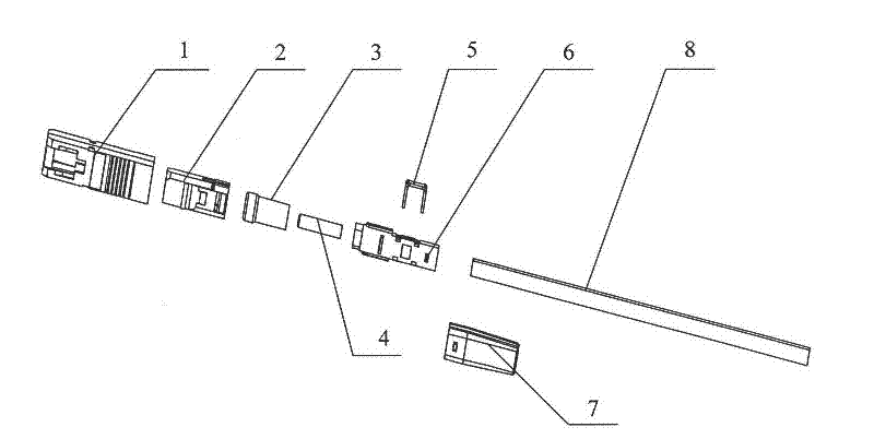
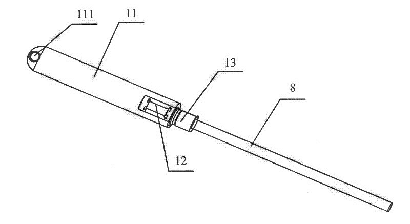
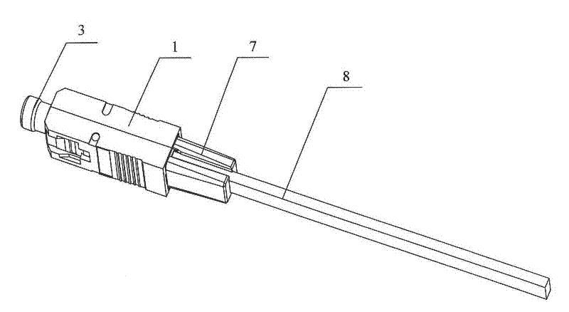
[0028] see Figure 1-Figure 3 , figure 1 Exploded view of the leather fiber optic connector provided by the embodiment of the present invention; figure 2 Schematic diagram of the structure of the leather thread insertion device provided by the embodi...


PUM


Abstract

The invention discloses a covered wire fiber connector which comprises the following parts: a caudal vertebra which is sleeved on a covered wire; a protection sleeve which is sleeved on the covered wire, inserted in the caudal vertebra and provided with a clamp hole; a covered wire clamp which is inserted in the clamp hole and is used for fixing the covered wire; a ceramic insertion core, whereinone end of the ceramic insertion core is inserted in the protective sleeve; a shell which is sleeved on an outside part of the protective sleeve, wherein one end of the shell is fixed on the caudal vertebra. By using the covered wire fiber connector to prepare a terminal of a covered wire optical cable at one end of the covered wire optical cable, when grinding detection is qualified, the shell is used to rapidly prepare a terminal which connects with a device, the other terminal is subjected to an welding operation with an outdoor optical cable in a fiber splitting box of or an optical cablecross-connecting box of a corridor. According to the invention, work efficiency is raised, investment cost is substantially reduced, a first installation success rate can reach 100%, and a length of the covered wire fiber connector can be customized according to a client requirement.

Description

technical field [0001] The invention relates to the technical field of optical fiber cold splicing in optical fiber transmission, and more specifically relates to a covered cable optical fiber connector. Background technique [0002] At the present stage, the optical cables used in the production of optical fiber connectors are indoor optical cables of φ3.0mm, φ2.0mm or φ0.9mm, but the optical fiber connectors made of such optical cables are mostly used in computer rooms. Due to their tensile strength, Poor anti-pressure and anti-torsion effects. Therefore, the fiber optic cable used for fiber-to-the-home is required to be a leather cable. The optical and mechanical properties of this fiber optic cable are all beyond the former. In the fiber-to-the-home project, there are two terminal methods, one is in the butterfly cable ( Hereinafter referred to as leather cable) on the end of the mechanical optical fiber quick connector to be directly connected to the ONU (Optical Netwo...

Claims


Application Information

Patent Timeline
IPC IPC(8): G02B6/38G02B6/44
Inventor 白秀彬
Owner 河北恒辉通信设备有限公司
Learn More