
Slurry mixing system as well as drainage pipe and cleaning method applied to same

A technology for mixing slurry and drainage pipes, which is applied in the directions of cleaning methods and utensils, chemical instruments and methods, cleaning hollow objects, etc., can solve the problems of wasting time and cost, affecting the mixing of mixed slurry, affecting the manufacture of semiconductor devices, etc.

Active Publication Date: 2013-08-14
SEMICON MFG INT (SHANGHAI) CORP +1
View PDF3 Cites 0 Cited by
  • Summary
  • Abstract
  • Description
  • Claims
  • Application Information

AI Technical Summary

Problems solved by technology

This method also has disadvantages. Periodic cleaning is only the estimated length of time set by the semiconductor device manufacturer, and the drain pipe will be blocked due to crystallization in the drain pipe. However, for the cleaning after different mixed slurries, the waste liquid produced The number of crystals in the drain is different, so the accumulation time of crystals in the drain is also different, so there will be two situations in regular cleaning, one is to clean before the accumulation of crystals in the drain, wasting time and cost; the other is The drainage pipe has been blocked and has not been cleaned at the set time, which will affect the cleaning of the mixing tank after mixing the next batch of mixed slurry. Both of these situations cannot guarantee that the semiconductor device manufacturer can clean the drainage pipe in a timely and accurate manner. , which will affect the mixing of the next batch of mixed slurry by the mixing tank, and ultimately affect the normal supply of the mixed slurry to the entire mixed slurry system, thereby affecting the manufacture of semiconductor devices

Method used


Image

  • Slurry mixing system as well as drainage pipe and cleaning method applied to same
  • Slurry mixing system as well as drainage pipe and cleaning method applied to same
  • Slurry mixing system as well as drainage pipe and cleaning method applied to same

Examples


Embodiment Construction

[0034] In order to make the object, technical solution and advantages of the present invention clearer, the present invention will be further described in detail below with reference to the accompanying drawings and examples.

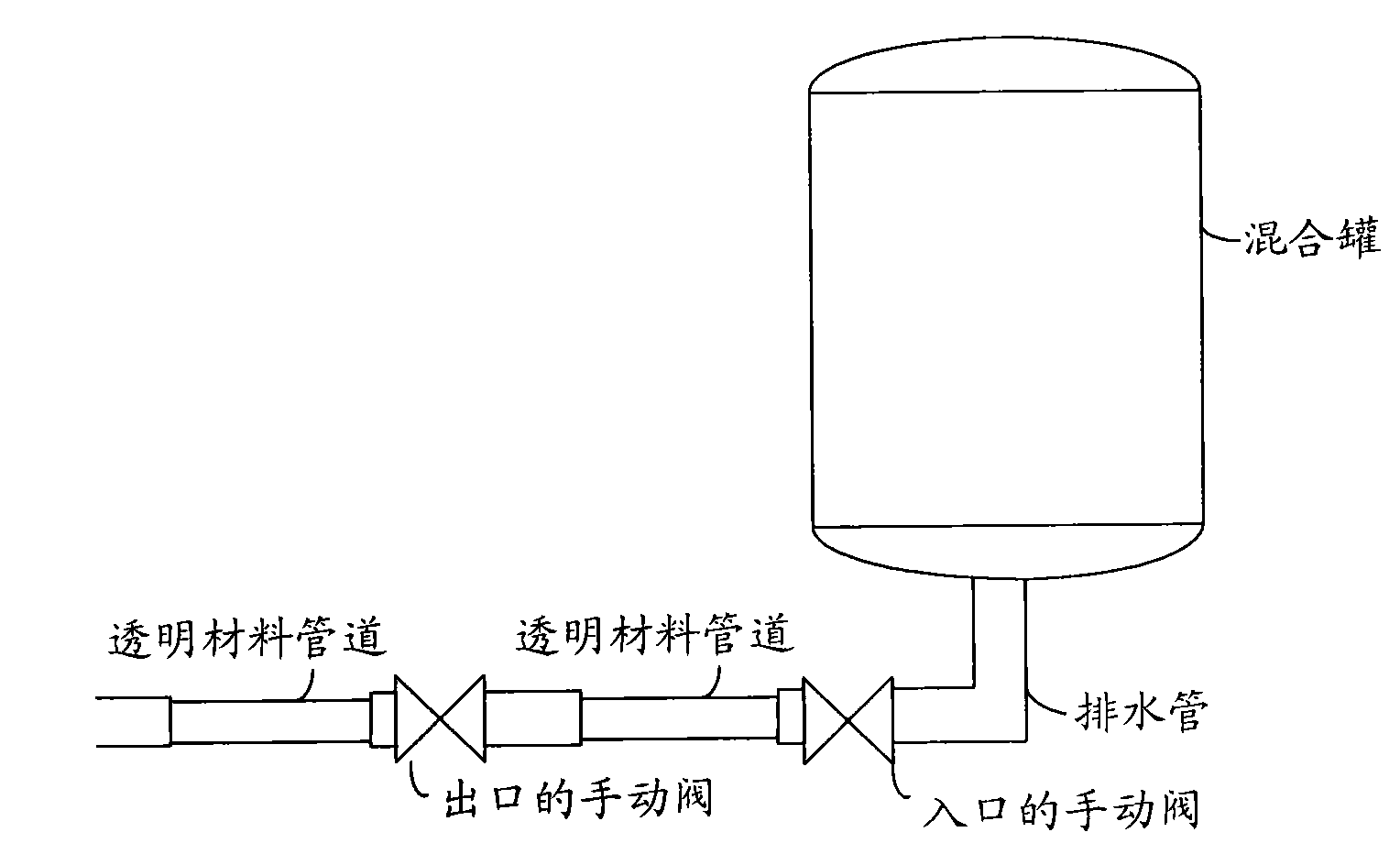
[0035] It can be seen from the prior art that the drainage pipes in the mixed slurry system can only be cleaned regularly or after they are completely blocked, and it is impossible to determine whether to clean them according to the current state of the drainage pipes. This is because the drainage pipes It is made of PP material, which is a non-transparent material, so it is impossible to monitor the amount of crystallization of the drain pipe in real time. Therefore, in order to clean the drainpipe timely and accurately, the present invention will not affect the mixing of the next batch of mixed slurry by the mixing tank, will not affect the normal supply of the mixed slurry by the entire mixed slurry system, and will not affect For the fabrication of ...


PUM


Abstract

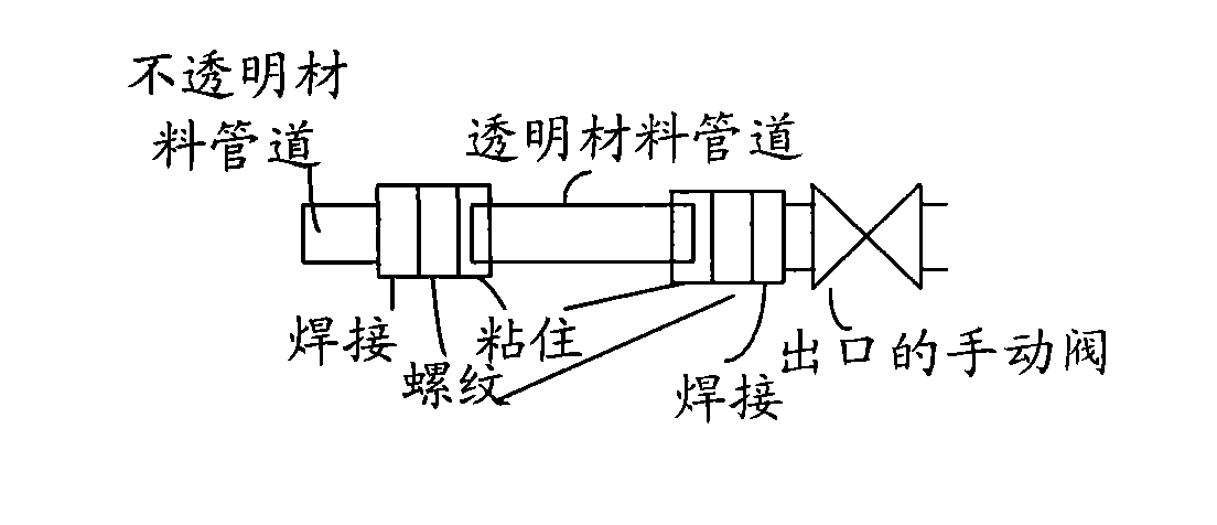
The invention discloses a slurry mixing system as well as a drainage pipe and a cleaning method applied to the same. The cleaning method comprises the steps of: connecting a transparent material pipeline into an inlet and / or outlet of a drainage pip in the slurry mixing system, judging whether the drainage pipe is blocked due to crystal accumulation in waste liquid or not by monitoring waste liquid flow rate in the transparent material pipeline and the ratio of the waste liquid flow rate in the transparent material pipeline and the flow rate in the waste liquid flow rate in the drainage pipe,and if so, immediately cleaning the drainage pipe. Alternatively, whether to clean the drainage pipe or not can also be determined according to monitored crystal amount in the transparent material pipeline. Accordingly, the drainage pipe can be timely and accurately cleaned with the cleaning method, the mixing of next batch of slurry to be mixed is not influenced, the slurry mixing system cannot be influenced in normal supply of the slurry to be mixed, and furthermore, the manufacturing of semiconductor devices cannot be influenced.

Description

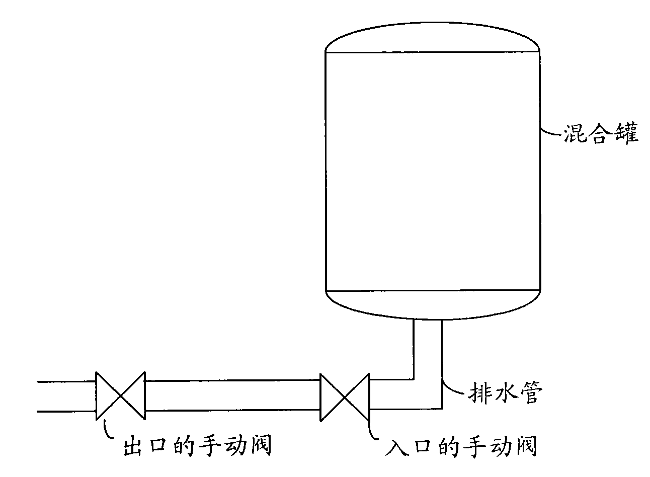
technical field [0001] The invention relates to the technical field of semiconductors, in particular to a slurry mixing system, a drainage pipe applied to the system and a cleaning method. Background technique [0002] In the manufacturing process of semiconductor devices, including the steps of cleaning and etching the wafer, it is necessary to process the wafer with corresponding mixed slurry. Therefore, semiconductor device manufacturing plants need a mixed slurry system to mix various pure solutions, and then apply the corresponding mixed slurry to the wafer cleaning process or wafer etching process. [0003] figure 1 It is a schematic cross-sectional structure diagram of an existing mixed slurry system, as shown in the figure, the system includes at least a mixing tank and a drain pipe, and of course, also includes a water inlet pipe (not shown in the figure), which has nothing to do with the content of this application, I won't go into details here. [0004] Among t...

Claims


Application Information

Patent Timeline
Patent Type & Authority Patents(China)
IPC IPC(8): H01L21/67B08B9/027
Inventor 胡晴朱江宁
Owner SEMICON MFG INT (SHANGHAI) CORP
Learn More