Energy router for distributed power generation

A distributed power generation and router technology, applied in the direction of circuit devices, AC network circuits, electrical components, etc., can solve problems such as inability to operate in parallel with the grid, and achieve the effect of safe and stable operation

Active Publication Date: 2012-01-11
INST OF ELECTRICAL ENG CHINESE ACAD OF SCI
View PDF5 Cites 48 Cited by
  • Summary
  • Abstract
  • Description
  • Claims
  • Application Information

AI Technical Summary

Problems solved by technology

However, the system is an off-grid system, which can only sup

Method used


Image

  • Energy router for distributed power generation
  • Energy router for distributed power generation

Examples


Embodiment Construction

[0022] The present invention will be further described below in conjunction with the accompanying drawings and specific embodiments.

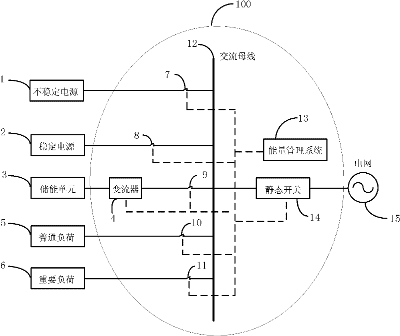
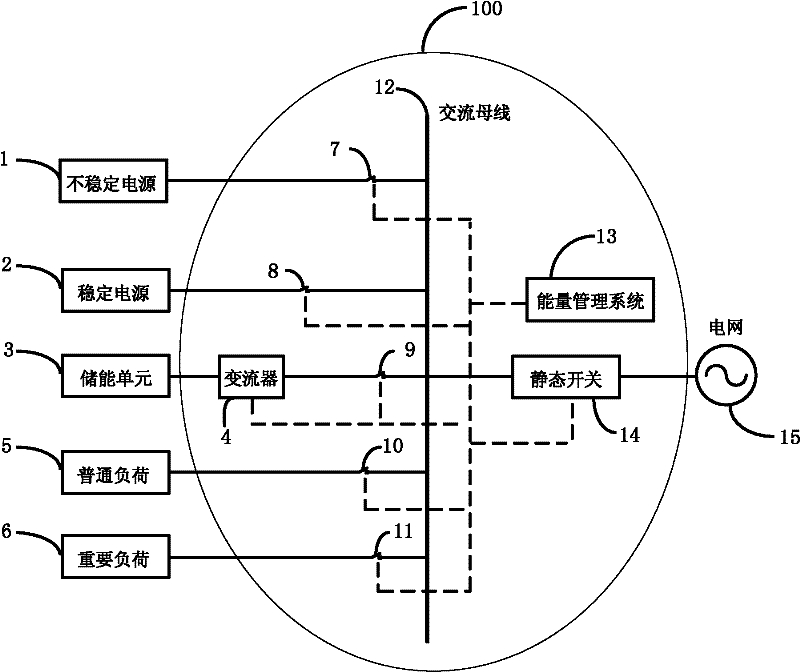
[0023] figure 1 Shown is a schematic structural diagram of a micro-grid system composed of an energy router 100 , a distributed power generation source, an energy storage unit 4 , a common load 5 and an important load 6 . The distributed power source mentioned therein includes an unstable power source 1 and a stable power source 2 .

[0024] Such as figure 1 As shown, an energy router 100 for distributed power generation includes controllable switches 7 - 11 , a converter 4 , an energy storage unit 3 , a power frequency AC bus 12 , an energy management system 13 and a static switch 14 .

[0025] One end of the first controllable switch 7 is connected to the unstable power supply 1, and the other end of the first controllable switch 7 is connected to the industrial frequency AC bus 12; one end of the second controllable switch 8 is connected t...


PUM


Abstract

The invention discloses an energy router for distributed power generation, which comprises a plurality of controllable switches, a current converter (4), an energy storage unit (3), a power frequency alternating current bus (12), an energy management system (13) and a static switch (14), wherein the controllable switches are connected onto the power frequency alternating current bus (12); the energy storage unit (3) is connected to the input side of the current converter (4); the output side of the current converter (4) is connected onto the controllable switches; one end of the static switch (14) is connected onto the power frequency alternating current bus (12); and the other end of the static switch (14) is connected to a public supply network (15). The energy management system (13) is connected with the controllable switches, the current converter (4) and the static switch (14) through an Ethernet. The energy management system provides a networking scheme, a stable control means and a load management strategy, so that the stable controllable alternating current electric energy is outputted after various instable power supplies are connected to the energy router.

Description

technical field [0001] The invention relates to an energy router, in particular to an energy router for coordinating and controlling various distributed power generation sources. Background technique [0002] As the disadvantages of the traditional centralized power supply mode become increasingly prominent, distributed power generation technology has been developing rapidly. Distributed power generation has the characteristics of flexibility, decentralization, small size, close to users and rational use of clean energy. It can improve the reliability of local power supply, reduce transmission loss, improve the utilization rate of primary energy and reduce exhaust emissions. It has a good application prospect. With the improvement of the technical level of distributed power generation, the continuous improvement of the performance and efficiency of various distributed power supply equipment, the application range of distributed power generation continues to expand, covering ...

Claims


Application Information

Patent Timeline
IPC IPC(8): H02J3/00
Inventor 唐西胜张国伟李宁宁裴玮齐智平
Owner INST OF ELECTRICAL ENG CHINESE ACAD OF SCI
Why Eureka
Try Eureka