Portable hydraulic steel bar bending machine

A kind of steel bar bending and portable technology, applied in the field of building construction tools, can solve the problems of easy fatigue of workers, high bending labor intensity, unable to meet the requirements of design specifications, etc., and achieve the effect of reasonable design and simple structure

Inactive Publication Date: 2012-01-18
CHINA RAILWAY FIRST GRP CO LTD
View PDF5 Cites 5 Cited by
  • Summary
  • Abstract
  • Description
  • Claims
  • Application Information

AI Technical Summary

Problems solved by technology

[0006] The purpose of the present invention is to overcome the deficiencies in the above-mentioned prior art, and provide a portable hydraulic steel bar bending machine, which has a simple structure, reasonable design, convenient operation and good use effect, and can effectively solve the bending labor intensity in the prior art. Large size, easy fatigue of workers and failure to meet the requirements of design specifications, and improve the bending quality and production efficiency, save labor, reduce the construction period, and at the same time easy to carry, low cost and wide range of use

Method used


Image

  • Portable hydraulic steel bar bending machine
  • Portable hydraulic steel bar bending machine
  • Portable hydraulic steel bar bending machine

Examples


Embodiment Construction

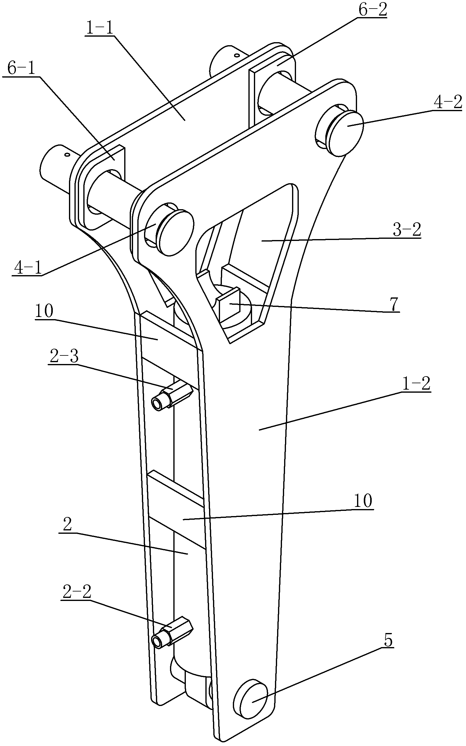
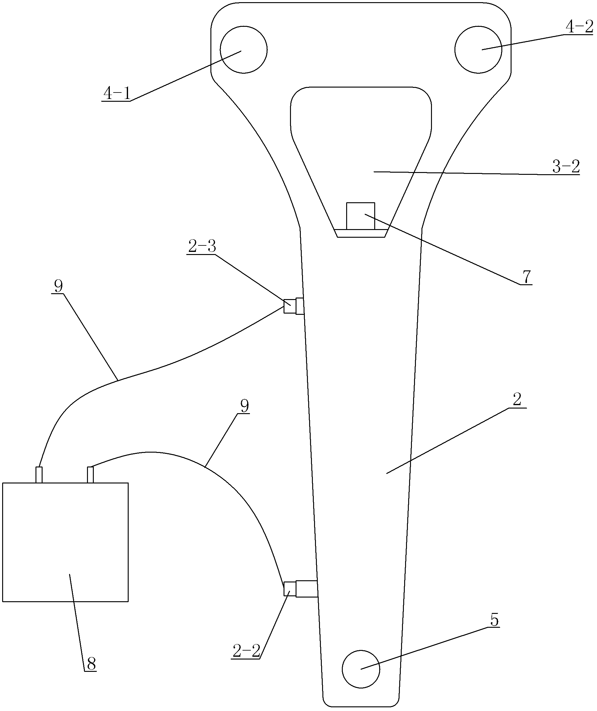
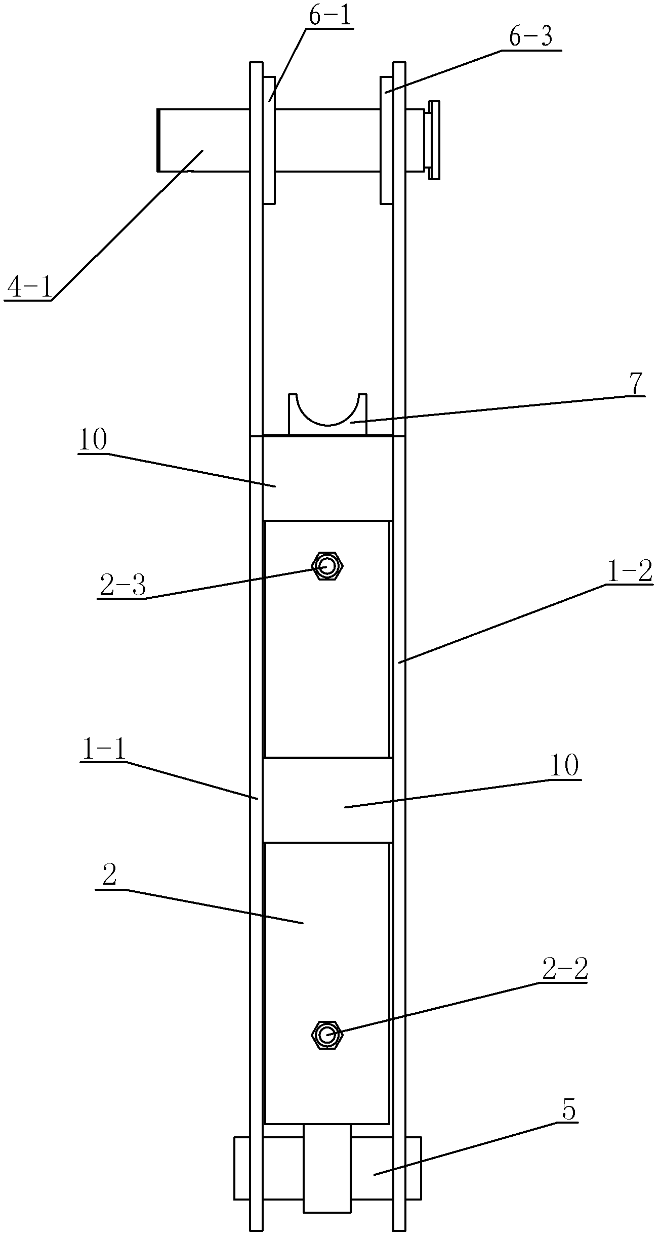
[0041] like figure 1 , figure 2 , image 3 , Figure 4 and Figure 5A portable hydraulic steel bar bending machine shown includes a support frame and a hydraulic cylinder 2, the support frame includes a left clip 1-1 and a right clip 1-2 arranged in parallel, and the hydraulic cylinder 2 is arranged on the left clip Between the sheet 1-1 and the right clip 1-2, the bottom of the hydraulic cylinder 2 is fixedly connected with the lower ends of the left clip 1-1 and the right clip 1-2 through the fixing piece 5, and the piston of the hydraulic cylinder 2 One end of the rod is fixedly installed with a support limiter 7 for supporting the steel bar to be bent and preventing the steel bar to be bent from moving left and right during the bending process. The limit forming part 1 4-1 and the limit forming part 2 4-2 are used to limit the two ends of the bending part of the steel bar to be bent and bend the steel bar to be bent. The limit forming part 1 4-1 and The limiting form...


PUM

PropertyMeasurementUnit
thicknessaaaaaaaaaa

Abstract

The invention discloses a portable hydraulic steel bar bending machine which comprises a support frame and a hydraulic oil cylinder, wherein the support frame comprises a left clamping piece and a right clamping piece which are arranged in parallel, the hydraulic oil cylinder is arranged between the left clamping piece and the right clamping piece, the bottom of the hydraulic oil cylinder is fixedly connected with the lower ends of the left clamping piece and the right clamping piece through a fixing part, a supporting and limiting part is fixedly mounted at one end of the piston rod of the hydraulic oil cylinder, a limiting and forming part I and a limiting and forming part II are arranged at the upper ends of the left clamping piece and the right clamping piece, the limiting and forming part I and the limiting and forming part II are arranged at the front and the back in parallel, the limiting and forming part I penetrates a through hole I arranged on the left clamping piece and a through hole III arranged on the right clamping piece, and is movably connected with the left clamping piece and the right clamping piece, and the limiting and forming part II penetrates a through hole II arranged on the left clamping piece and a through hole IV arranged on the right clamping piece, and is movably connected with the left clamping piece and the right clamping piece. The portable hydraulic steel bar bending machine is simple in structure, reasonable in design and convenient to use and operate, and can be used for reducing the labor intensity and improving the bending quality; and simultaneously, the portable hydraulic steel bar bending machine is convenient to carry and wide in range of applications.

Description

technical field [0001] The invention relates to a building construction tool, in particular to a portable hydraulic steel bar bending machine. Background technique [0002] In the process of building construction, it is necessary to widely use reinforced concrete structures. The reinforced concrete structure is formed by binding steel bars into a skeleton and then pouring concrete. That is, before concrete pouring, the steel bars must be bound into a skeleton. The steel bars sold on the market are all standard specifications. When used, it is necessary to cut the steel bars to the required length on site and bend the steel bars as required. [0003] In the prior art, the bending of steel bars in construction is usually carried out by manual forced bending or thermal bending. Among them, manual forced bending is extremely labor-intensive and time-consuming, and it is difficult to meet the requirements of design specifications; The part of the bent steel bar that needs to be ...

Claims


Application Information

Patent Timeline
Patent Type & Authority Applications(China)
IPC IPC(8): B21F1/00
Inventor 范恒秀祁润平景兆德赵金鹏王高平李生龙杨伟锋杨洋刘涛
Owner CHINA RAILWAY FIRST GRP CO LTD
Why Eureka
Try Eureka