Clamp device for carrying out groove milling on wheel disk of gas turbine

A gas turbine and fixture device technology, applied in positioning devices, clamping, manufacturing tools, etc., can solve problems such as difficult positioning and clamping, and achieve the effects of simple structure, convenient use, and easy manufacturing

Inactive Publication Date: 2012-01-18
HARBIN TURBINE
View PDF5 Cites 5 Cited by
  • Summary
  • Abstract
  • Description
  • Claims
  • Application Information

AI Technical Summary

Problems solved by technology

[0003] The purpose of the present invention is to solve the problem of difficult positioning and clamping of the existing gas turbine disc during the processing process, and further provide a fixture device for milling the gas turbine disc

Method used


Image

  • Clamp device for carrying out groove milling on wheel disk of gas turbine
  • Clamp device for carrying out groove milling on wheel disk of gas turbine
  • Clamp device for carrying out groove milling on wheel disk of gas turbine

Examples


specific Embodiment approach 1

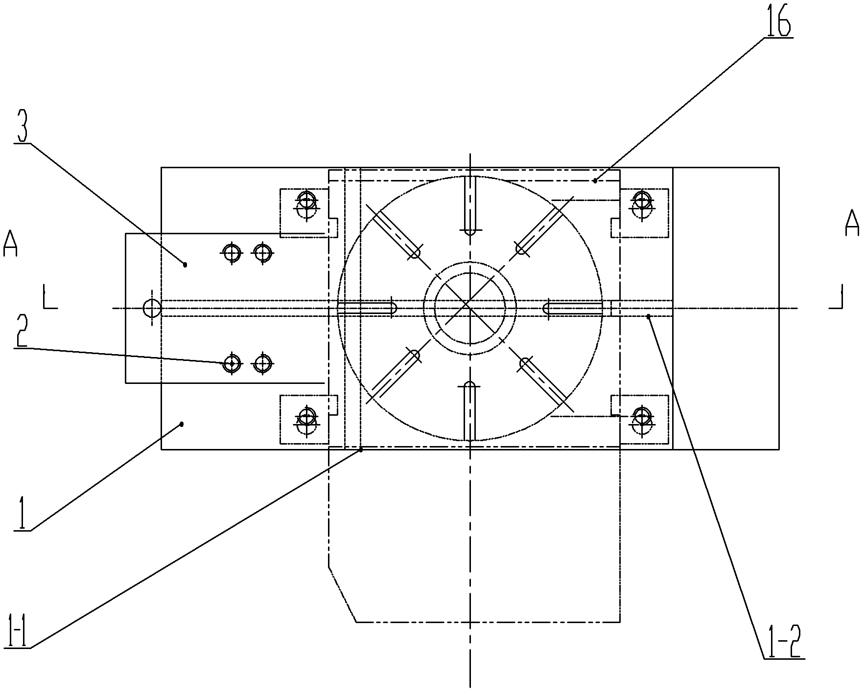
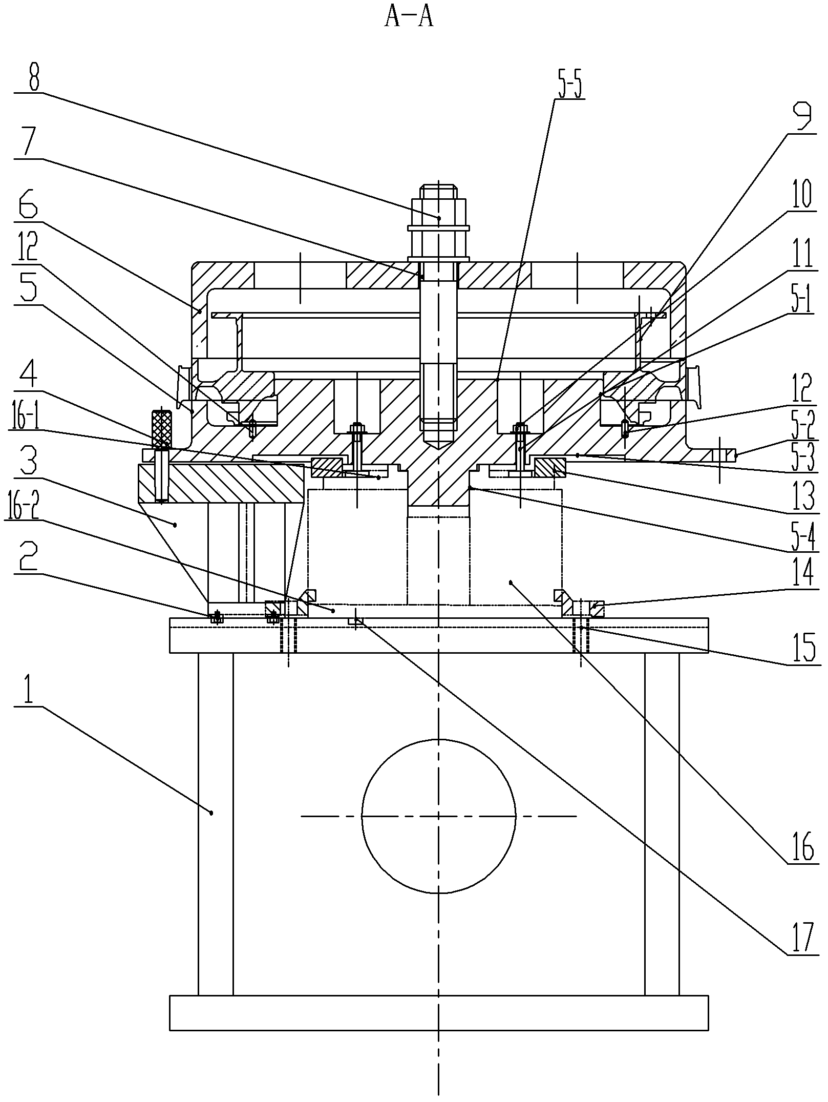
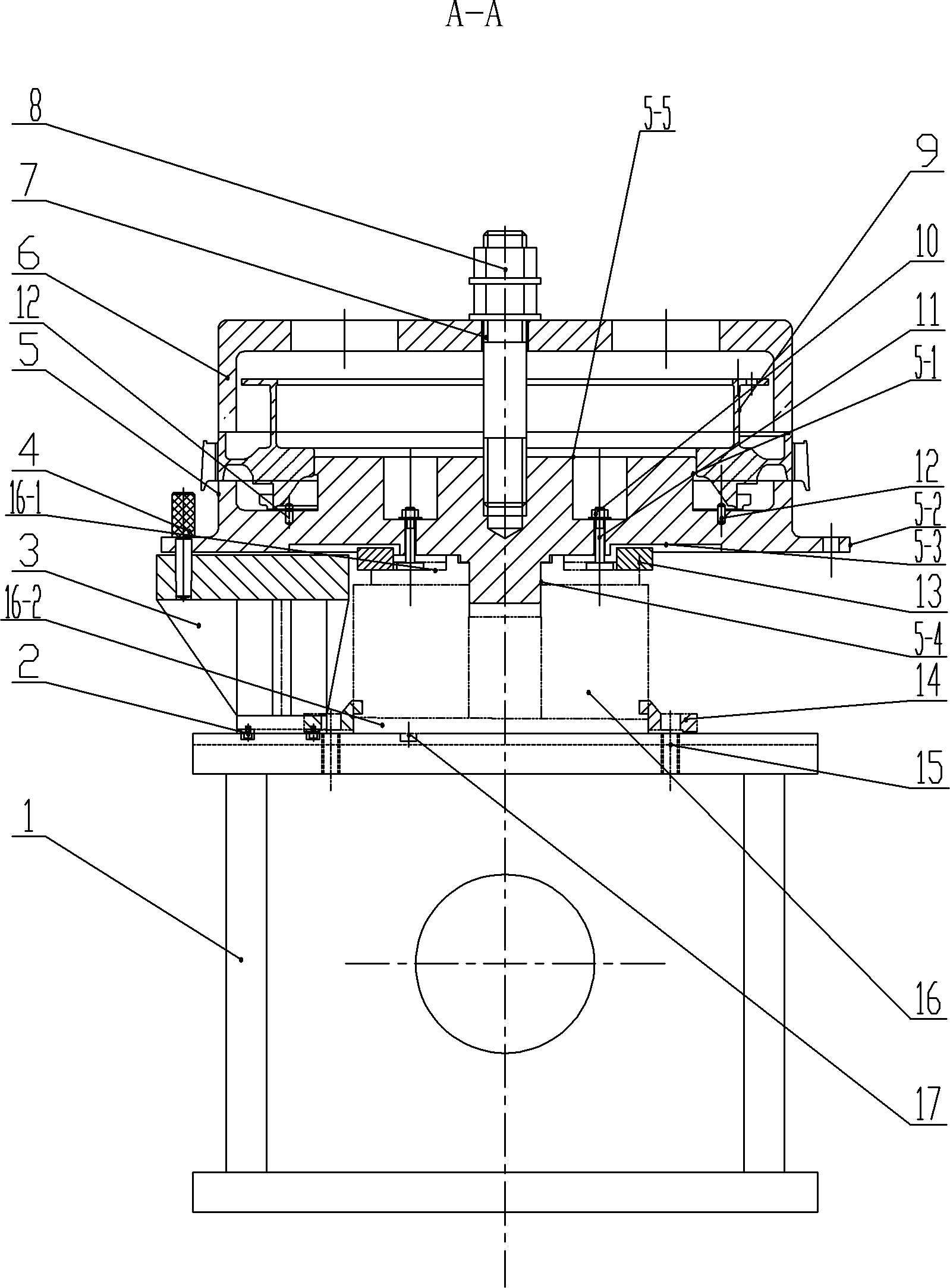
[0007] Specific embodiment one: combination figure 1 with figure 2 To explain this embodiment, a clamp device for milling grooves in a gas turbine wheel disc includes a base 1, a support frame 3, a positioning pin 4, a clamp body 5, a gland 6, a double-ended screw 7, a nut 8, and a The indexing table 16, a plurality of positioning pins 12, a plurality of first positioning keys 13 and a plurality of pressing plates 14, the base 1, the indexing table 16, the clamp body 5 and the pressing cover 6 are arranged from bottom to top, the base 1 and the indexing table 16 is fixed by a plurality of pressing plates 14, the indexing table 16 and the clamping body 5 are positioned by a plurality of first positioning keys 13, the clamping body 5 and the pressing cover 6 are positioned by a plurality of positioning pins 12, and the clamping The concrete 5 and the gland 6 are fixed by a double-headed screw 7 and a nut 8. The supporting frame 3 is arranged between the base 1 and the clamping b...

specific Embodiment approach 2

[0010] Specific implementation manner two: combination figure 1 with figure 2 To illustrate this embodiment, a clamp device for milling grooves in a gas turbine wheel disc of this embodiment further includes a plurality of second positioning keys 17, and the base 1 is provided with a first key groove 1-1 and a second key groove 1-2, A third keyway 16-1 and a fourth keyway 16-2 are opened on the bottom surface of the indexing table 16. The first keyway 1-1 is matched with the third keyway 16-1, and the second keyway 1-2 and the fourth keyway 16 -2 is matched, the first keyway 1-1 and the third keyway 16-1 and the second keyway 1-2 and the fourth keyway 16-2 are positioned and connected by a plurality of second positioning keys 17. This arrangement facilitates the precise positioning of the base 1 and the indexing table 16. The other composition and connection relationship are the same as in the first embodiment.

specific Embodiment approach 3

[0011] Specific implementation mode three: combination figure 1 with figure 2 To describe this embodiment, the lower end of the support frame 3 of this embodiment is fixedly mounted on the base 1. This setting facilitates the precise positioning of the entire fixture. The other composition and connection relationship are the same as in the second embodiment.


PUM


Abstract

The invention discloses a clamp device for carrying out groove milling on a wheel disk of a gas turbine and relates to a clamp device. The invention solves the problem of difficulty in positioning and clamping in the machining process of the wheel disk of the existing gas turbine. A base (1), an indexing table (16), a clamp body (5) and a gland (6) of the clamp device are arranged sequentially from bottom to top. The base (1) and the indexing table (16) are relatively fixedly arranged through a plurality of pressure plates (14). The indexing table (16) and the clamp body (5) are relatively positioned through a plurality of positioning keys (13). The clamp body (5) and the gland (6) are relatively positioned through a plurality of positioning pins (12). The clamp body (5) and the gland (6) are relatively fixed through a double-thread screw (7) and a nut (8). A support frame (3) is arranged between the base (1) and the clamp body (5). The clamp body (5) and the support frame (3) are relatively positioned through a positioning inserted pin (4). The clamp device is suitable for the positioning and clamping of the wheel disks of various types of gas turbines.

Description

Technical field [0001] The invention relates to a clamp device, in particular to a clamp device used for slot milling of a gas turbine wheel disc. Background technique [0002] Gas turbine roulette wheel groove profile requires high precision, and there are the following technical difficulties: the roulette structure is complex and difficult to clamp; the roulette mechanism is thin, the rigidity is not good, and the processing is prone to vibration and deformation; the material of the roulette is high-speed alloy steel, which is processed Sex is not good. The roulette can be milled. The roulette is required to be connected and tightened with the indexing device through a clamp. Due to the high hardness of the product roulette, it has to withstand a large cutting force during processing. After the roulette is installed, it is required to have sufficient clamping force to clamp to ensure that the roulette does not vibrate during processing. In summary, the existing gas turbine w...

Claims


Application Information

Patent Timeline
Patent Type & Authority Applications(China)
IPC IPC(8): B23Q3/00
Inventor 储继影太秀滨张俊成关占群訾凯松逯丹
Owner HARBIN TURBINE
Why Eureka
Try Eureka