
Emptying frame

A technology of unwinding rack and moving rack, which is applied in thin material processing, coiling strips, transportation and packaging, etc., can solve the problems of complicated process of placing steel coils, inaccurate control of precision, difficulty in correction and adjustment, etc. The effect is good, the overall structure is small, and the effect of avoiding risk factors

Active Publication Date: 2012-01-18
SUZHOU JINTONG MACHINERY MFG
View PDF5 Cites 16 Cited by
  • Summary
  • Abstract
  • Description
  • Claims
  • Application Information

AI Technical Summary

Problems solved by technology

[0002]The unwinding rack is mainly used in the product equipment of coil material processing and manufacturing, for placing the coil material and correcting its position, especially in applications such as steel For coils and other coils, because the material is relatively heavy, and the commonly used unloading rack is relatively tall, the steel coil needs to be placed at a high position when hoisting, which is more dangerous, and the process of placing the steel coil is more complicated and cumbersome
In addition, when the steel coil deviates, it is necessary to manually adjust the deviation of the steel coil, and the steel coil itself is relatively heavy and is still in a high position, which not only makes the deviation correction difficult, but also quite dangerous. inaccurate control
In addition, the steel coil tensioning device generally uses hydraulic or manpower, the hydraulic noise is relatively large, and oil leakage is prone to occur, and the manual tensioning is also quite laborious and cumbersome.

Method used


Image

  • Emptying frame
  • Emptying frame
  • Emptying frame

Examples


Embodiment Construction

[0016] The preferred embodiments of the present invention will be described in detail below in conjunction with the accompanying drawings, so that the advantages and features of the present invention can be more easily understood by those skilled in the art, so as to define the protection scope of the present invention more clearly.

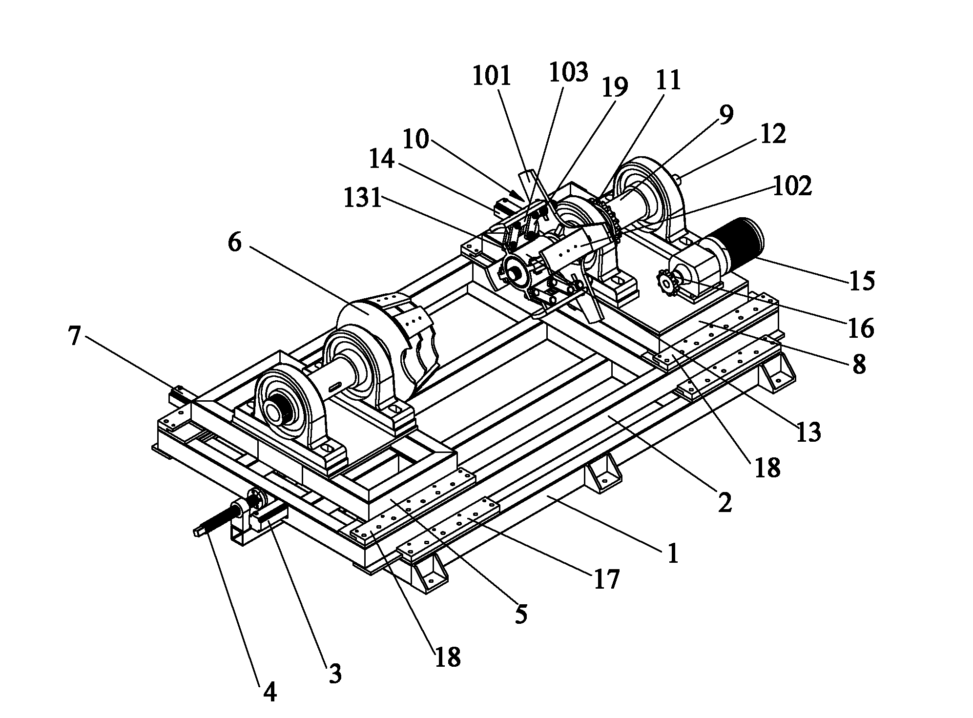
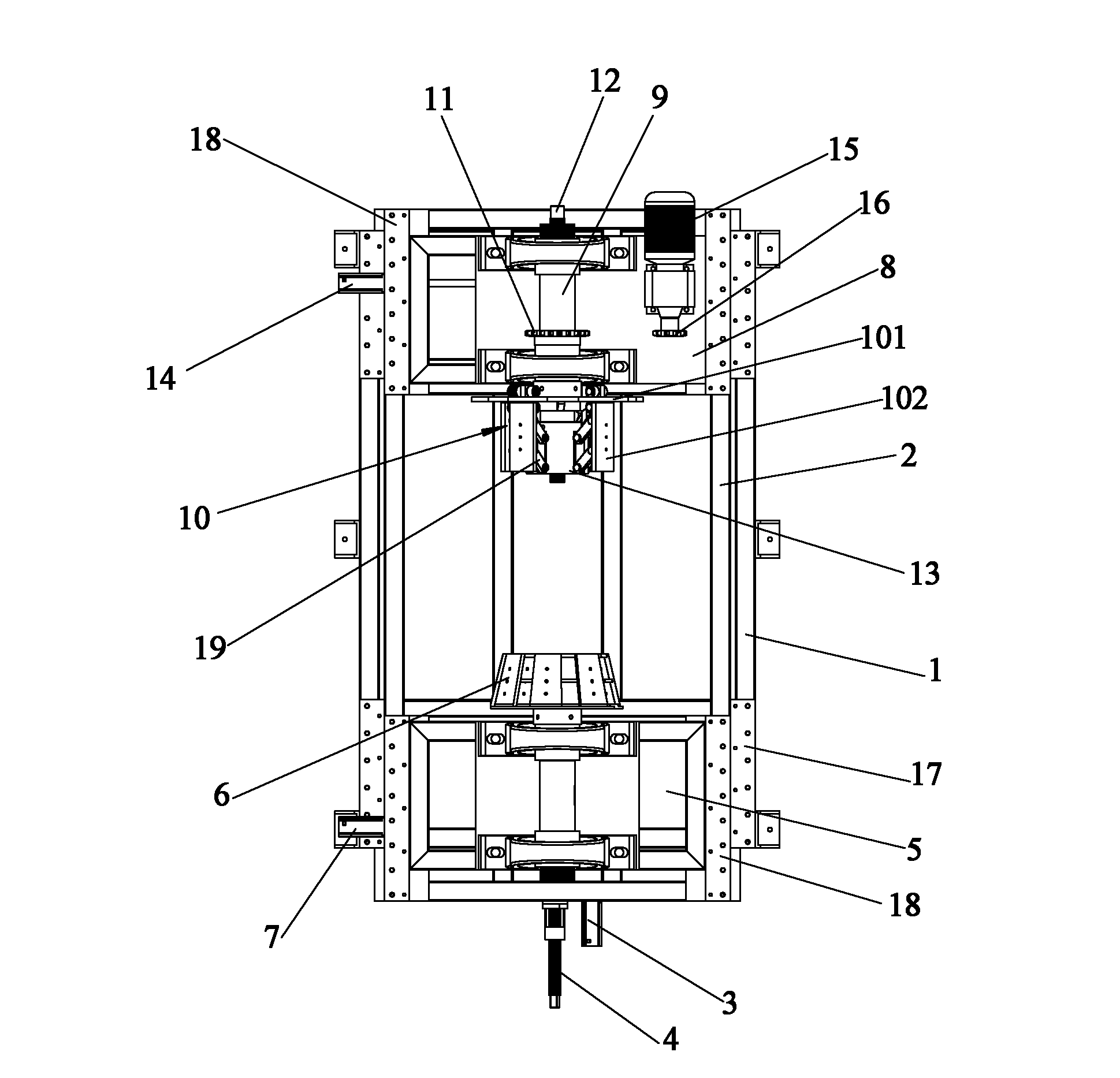
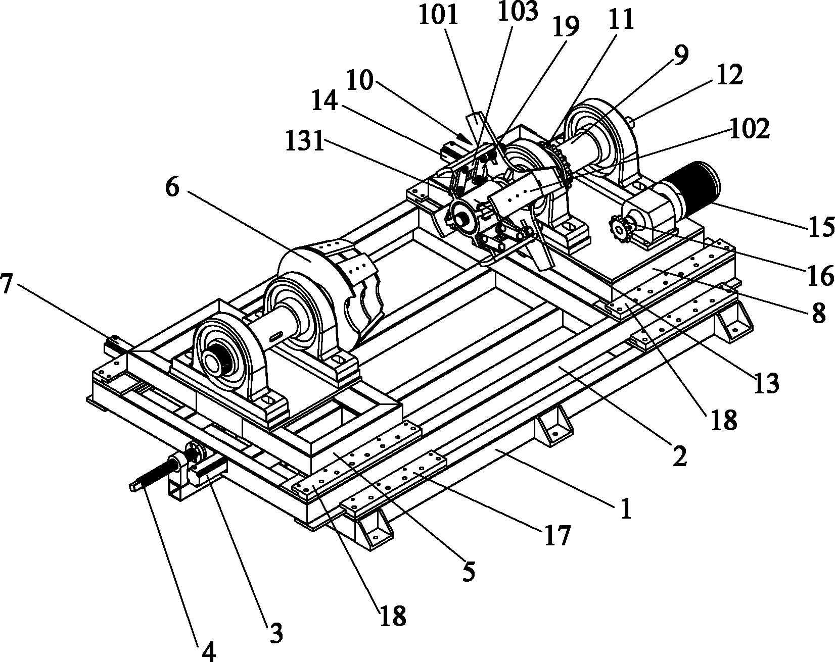
[0017] Referring to the accompanying drawings, the discharge rack of the present invention includes a fixed base 1, on which a first movable frame 2 for adjusting the position of the coil is slidably provided, and two first moving frames 2 are respectively provided on both sides of the fixed base 1. Clamp 17, the inboard portion of clamp 17 is provided with opening, and this first mobile frame 2 is sandwiched in the opening of the internal portion of clamp 17 and moves left and right on fixed base 1, and one side end portion of first mobile frame 2 is provided with With a first motor 3 for automatically adjusting the position of the first mobile f...


PUM


Abstract

The invention provides an emptying frame, comprising a fixed base. The fixed base is provided with a first moving frame for adjusting the positions of coiled materials in a sliding manner; one end part of the first moving frame is provided with a second moving frame in a sliding manner; the second moving frame is provided with a tightening wheel device for tightening the coiled materials; the other end part of the first moving frame is provided with a third moving frame in a sliding manner; the third moving frame is provided with a rotating drum which is provided with a tensioning wheel device for tensioning the coiled materials; the rotating drum is internally sheathed with a tensioning screw rod for manually adjusting the tensioning force to the coiled materials; the tensioning wheel device can be adjusted by the tensioning screw rod so as to be suitable for the coiled materials with different sizes; and the emptying frame is also provided with a motor capable of emptying the coiledmaterials automatically. In the emptying frame, the bearing performance is good, the coiled materials can be automatically emptied, so that the working efficiency is improved and the noise caused by using hydraulic pressure is avoided. The emptying frame can be applicable to products with different sizes and can be widely applied.

Description

technical field [0001] The invention relates to a coil material discharging rack, more particularly to an electric discharging rack. Background technique [0002] The unwinding rack is mainly used in the product equipment of coil processing and manufacturing, and is used to place the coil and adjust its position, especially when it is applied to coils such as steel coils, because the material is relatively heavy, it is commonly used The unloading rack is relatively tall, and the steel coil needs to be placed at a very high position during hoisting, which is more dangerous, and the process of placing the steel coil is more complicated and cumbersome. In addition, when the steel coil deviates, it is necessary to manually adjust the deviation of the steel coil, and the steel coil itself is relatively heavy and is still in a high position, which not only makes the deviation correction difficult, but also quite dangerous. The controls are also not accurate. In addition, the ste...

Claims


Application Information

Patent Timeline
Patent Type & Authority Applications(China)
IPC IPC(8): B65H16/06B65H23/032
Inventor 蒋明生
Owner SUZHOU JINTONG MACHINERY MFG
Learn More