Clasping device for fitting up steel pipe sleeve and construction method thereof

A clamping device and sleeve technology, which is applied in the field of holding clamping devices for steel pipe casing groups, can solve the problems of uneven speed, damage to support brackets, etc., and achieve the effects of uniform speed, simple device, and convenient use

Inactive Publication Date: 2012-01-18
CHINA CONSTR SENVENTH ENG BUREAU INSTALLATION ENG
View PDF6 Cites 8 Cited by
  • Summary
  • Abstract
  • Description
  • Claims
  • Application Information

AI Technical Summary

Problems solved by technology

[0003] The technical problem to be solved by the present invention is that when the steel sleeve steel pipe is installed, the uneven speed during the dragging pro

Method used


Image

  • Clasping device for fitting up steel pipe sleeve and construction method thereof
  • Clasping device for fitting up steel pipe sleeve and construction method thereof
  • Clasping device for fitting up steel pipe sleeve and construction method thereof

Examples


Embodiment Construction

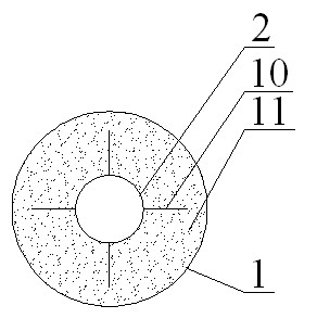
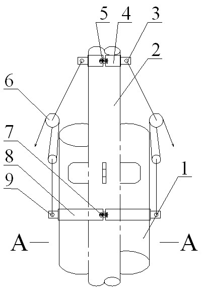
[0015] A clamping device for pairing of steel pipe casing groups, comprising an inner tube clamp 4 and an outer tube clamp 8, the inner tube clamp 4 is fixed by fastening bolts Ⅰ5, the outer tube clamp 8 is fixed by fastening bolts Ⅱ7, and the inner tube clamp 8 is fixed by fastening bolts Ⅱ7. Two symmetrical hoisting holes I3 are provided on the pipe holding card 4, and two symmetrical hoisting holes II9 are provided on the outer pipe holding card 8, and the lifting device 6 is installed on the lifting holes I3 and II9.

[0016] The lifting device is an electric hoist or a manual hoist or a pulley block.

[0017] The construction method of the clamping device for the steel pipe casing group pair has the following steps:

[0018] (1) Install the outer casing between the two valve wells, then fasten the outer pipe on the outer casing, and install one end of the lifting device on the hoisting hole II where the outer pipe is held;

[0019] (2) Assemble the first section of the i...


PUM


Abstract

The invention discloses a clasping device for fitting up a steel pipe sleeve, which comprises internal pipe clasps and external pipe clasps, wherein the internal pipe clasps are fixed through a fastening bolt I and the external pipe clasps are fixed through a fastening bolt II; the internal pipe clasps are provided with two symmetrical hosting holes I; the external pipe clasps are provided with two symmetrical hosting holes II; and lifting devices are arranged on the hosting holes I and the hosting holes II. The clasping device has a simple structure and is convenient to use; and internal pipes of the steel pipe sleeve can be arranged in an external sleeve sequentially through the lifting devices so that less machines are needed in the construction, the internal pipes are pulled into the external sleeve at a uniform speed, the stress direction of the internal pipes is consistent to the central line of a pipeline, and supports on the internal pipes cannot be damaged.

Description

technical field [0001] The invention relates to a clamping device and a construction method for steel pipe casing group pairing. Background technique [0002] At present, steel sheathed steel pipes are generally assembled on site with loaders or tractors to drive wire ropes to drag the inner pipe into the outer casing. During construction, a hook is installed at both ends of the steel wire rope, one end of the steel wire rope is hung on the loader, and the other end is hung on the inner tube mouth, and the loader or tractor is started to drag the inner tube into the outer tube. Due to the non-uniform acceleration when the loader or tractor is started, sometimes the speed changes greatly during the dragging process, and the direction also changes. When dragging, it is easy to damage part of the support bracket on the inner casing. Contents of the invention [0003] The technical problem to be solved by the present invention is that during the installation of the steel slee...

Claims


Application Information

Patent Timeline
IPC IPC(8): B66C1/48B23P21/00
Inventor 王五奇靳宏伟王同生魏肖琦王登武靳小英屈国庆
Owner CHINA CONSTR SENVENTH ENG BUREAU INSTALLATION ENG
Why Eureka
Try Eureka