Vibratory stress relief apparatus for medium frequency and low frequency shaft type parts, and use method thereof

A technology of shaft parts and vibration aging, which is applied in the direction of furnace types, furnaces, heat treatment equipment, etc., can solve problems such as poor effect, inability to obtain dynamic stress for rolls, and difficulty in reducing residual stress, so as to achieve deformation guarantee and dynamic stress distribution uniform effect

Inactive Publication Date: 2012-01-18
GUANGXI UNIV
View PDF6 Cites 22 Cited by
  • Summary
  • Abstract
  • Description
  • Claims
  • Application Information

AI Technical Summary

Problems solved by technology

Therefore, regardless of whether it deals with low frequency or high frequency, the excitation frequency is carried out according to the natural frequency of the system. The excitation frequency is actually lower than the natural frequency of bending vibration of the roll itself, so that the roll cannot obtain enough dynamic stress to eliminate its internal vibration. Residual Stress
[0004] In short, the effect of the current vibration aging device for shaft parts is poor, and it is difficult to achieve the expected effect of reducing residual stress

Method used


Image

  • Vibratory stress relief apparatus for medium frequency and low frequency shaft type parts, and use method thereof
  • Vibratory stress relief apparatus for medium frequency and low frequency shaft type parts, and use method thereof
  • Vibratory stress relief apparatus for medium frequency and low frequency shaft type parts, and use method thereof

Examples


Embodiment 1

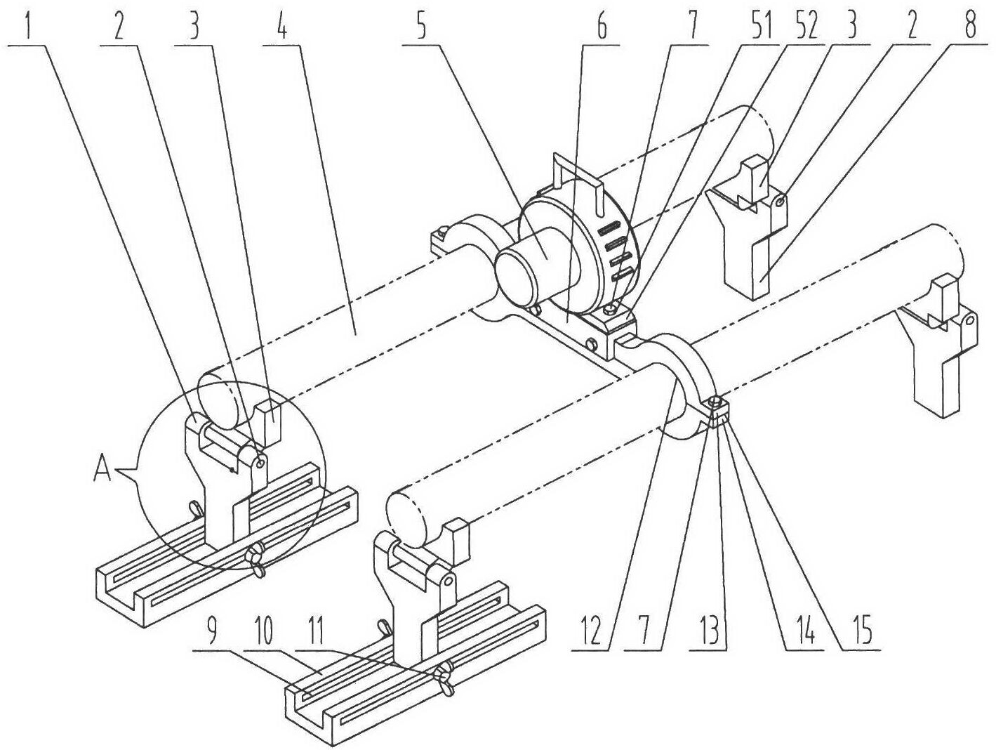
[0029] like figure 1 As shown, the vibration aging device for shaft parts according to the present invention is composed of a vibrator 5, an exciter base, a clamping block 3 and a supporting mechanism.

[0030] The bottom end of the exciter 5 is provided with a connection plate 52, and two connection holes 51 are opened on the connection plate 52. There are two screw holes corresponding to the hole 51, screw the bolt 7 through the connecting hole 51 on the connecting plate 52 into the screw hole of the upper bottom cover, and then the vibrator 5 can be fixed on the middle position of the upper bottom cover 13 , the two ends of the upper bottom cover 13 are arc-shaped notches 12, the edge of the notch 12 is provided with a protruding flat plate 15, and a through hole is opened on the flat plate 15, and the structure of the lower bottom plate 14 is similar to that of the upper bottom cover 13. The upper bottom cover 13 and the lower bottom plate 14 are combined with the upper b...

Embodiment 2

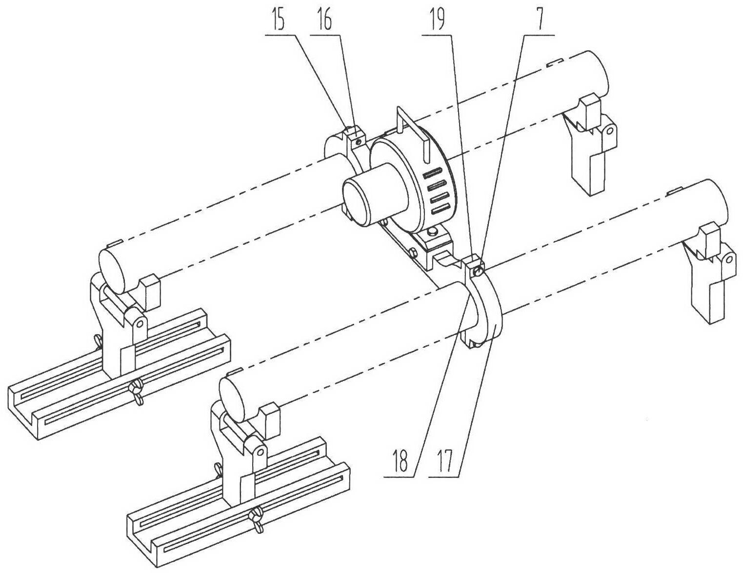
[0034] like image 3 As shown, the specific structure of another embodiment of the present invention, this embodiment is different from Embodiment 1 in that the main exciter bottom 6 includes a fork bar 16, a left end cover 15, and a right end cover 17, and the fork bar 16 is open at both ends. There is an arc-shaped fork 18 (from the figure, the position of the lead wire of 18 should be moved into the fork), the two ends of the fork 18 have radially outwardly protruding extensions 19, and there are through holes on the extension plate 19 , the left end cap 15 and the right end cap 17 are arc-shaped, and the openings are also arc-shaped to match the fork 18. The two ends of the left end cap 15 and the right end cap 17 are also provided with radially outwardly protruding extensions. The plate 19 and the extension plate 19 have through holes, and the left end cover 15 and the right end cover 17 are fixed on the fork bar 16 by bolts, and the fork bar 16 can be fixed on the shaft ...


PUM


Abstract

The invention relates to a vibratory stress relief apparatus for medium frequency and low frequency shaft type parts, and a use method thereof. The apparatus comprises a vibration exciter, a support block for clamping and supporting a workpiece, and a support mechanism connected with the support block. The support mechanism comprises a pair of support frames comprising a left support frame and a right support frame, and a support seat for installing the left support frame and the right support frame, wherein the left support frame and the right support frame right are arranged relatively. Thesupport block respectively forms rotatable connections with the left support frame of the support mechanism and the right support frame of the support mechanism. The apparatus further comprises a vibration exciter base for installing the vibration exciter, wherein the vibration exciter base is arranged on the middle portion of the workpiece, the vibration exciter, the vibration exciter base and the workpiece synchronously vibrate during vibratory stress relief. According to the present invention, a simply supported beam form is adopted, the flexural vibration type primary resonance is generated by the shaft type parts under the excitation of the vibration exciter at the natural frequency adopted for shaft flexural vibration; in the prior art, the dynamic stress generated by the apparatus does not reach the requirement of residual stress decreasing, with the apparatus provided by the present invention, the problem in the prior art is solved; the deformation amounts on both ends of the shaft are substantially improved; the dynamic stress distribution of the shaft is uniform so as to effectively reduce the residual stress of the shaft part.

Description

technical field [0001] The invention relates to a vibration aging device, in particular to a vibration aging device for shaft parts used for reducing the residual stress of middle and low frequency shaft parts whose bending vibration natural frequency is less than 200HZ. Background technique [0002] Vibration aging technology is a method to eliminate the residual stress inside the workpiece. Through vibration, when the superposition of the residual stress inside the workpiece and the dynamic stress generated by vibration reaches or exceeds the yield strength of the material, the material undergoes a small amount of plastic deformation, so that the material The internal stress can be relaxed and relieved. Compared with thermal aging, vibration aging has the advantages of less investment, quick effect, low operating cost and environmental protection. Therefore, the high technology of vibration aging has broad application prospects. [0003] However, many current vibration a...

Claims


Application Information

Patent Timeline
Patent Type & Authority Applications(China)
IPC IPC(8): C21D9/28C21D9/30C21D10/00
Inventor 蔡敢为李岩舟黄院星农慧李兆军
Owner GUANGXI UNIV
Why Eureka
Try Eureka