Supercharge Your Innovation With Domain-Expert AI Agents!

Sliding block guiding hydraulic cutting knife

A formal and hydraulic technology, applied in wellbore/well components, earthwork drilling and mining, etc., can solve problems such as poor cutting effect, low success rate and sequence, and high labor intensity of manual operators, achieving high success rate and compact structure , small size effect

Inactive Publication Date: 2013-08-28
山东正元地质资源勘查有限责任公司
View PDF6 Cites 0 Cited by
  • Summary
  • Abstract
  • Description
  • Claims
  • Application Information

AI Technical Summary

Problems solved by technology

[0003] The purpose of the present invention is to overcome the deficiencies of the above-mentioned prior art, and provide a hydraulic cutter guided by a slider, which mainly solves the problem of poor cutting effect, low success rate and sequence, and labor intensity of manual operators in existing small-diameter inclined hole drilling. Major and other issues

Method used


Image

  • Sliding block guiding hydraulic cutting knife
  • Sliding block guiding hydraulic cutting knife
  • Sliding block guiding hydraulic cutting knife

Examples


Embodiment 1

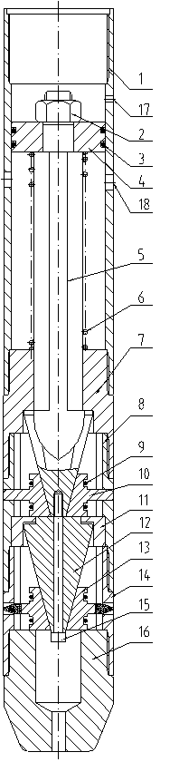
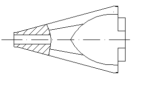
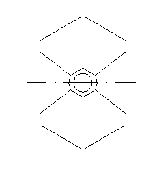
[0015] Example 1, see figure 1 , figure 2 , image 3 , Figure 4 , Figure 5 , Image 6 , processed into short pipe 1, spring seat 7, guide body 8, knife rest 14, guide head 16, and the five are connected with threads; overflow hole 17 and pressure relief hole 18 are set on the wall of short pipe 1, overflow Orifice 17 is to prevent the mud pump pressure from being too high, and pressure relief hole 18 is to relieve pressure when the pipe is cut; a piston 4, a spring 6 and a piston rod 5 are installed in the short pipe 1, and the top of the piston 4 and the piston rod 5 passes through The bolt 2 is connected, the spring 6 is set outside the piston rod 5, and is located between the piston 4 and the spring seat 7, the piston 4 can slide up and down in the short tube 1 under the action of hydraulic force and elastic force, and the spring 6 can make the piston 4 return, An O-ring 3 is installed between the piston 4 and the short tube 1; a guide block 10, a vertebral body 12 ...


PUM


Abstract

The invention discloses a sliding block guiding hydraulic cutting knife. The knife is characterized by comprising a short pipe (1), a spring seat (7), a guiding body (8), a knife rest (14) and a guiding head (16) which are in threaded connection, wherein the short pipe (1) is provided with an overflow hole (17) and a pressure relief hole (18); a piston (4), a spring (6) and a piston rod (5) are arranged in the short pipe (1); a guiding block (10) is arranged in the guiding body (8); a cone (12) and a knife head (13) are arranged in the knife rest (14); the guiding block (10) is fixed at the bottom end of the piston rod (5) through a lock spring (9); the cone (12) is connected with the piston rod (5) through an inner hexagonal bolt (15); and the knife head (13) is fixed at the lower end ofthe cone (12) through the lock spring. The knife has a compact structure and small volume; and a drill rod is rotated, the piston is pushed to move downwards by drilling fluid serving as power, the lower end of the piston rod pushes the guiding block to move transversely and support and rub the inner wall of a cut pipe to achieve a guiding effect, the cone pushes the knife head to move outwards to cut the pipe, and the knife head gradually cuts the pipe along with the continuous wear of the guiding block and the inner wall of the cut pipe until the pipe is cut off.

Description

technical field [0001] The invention relates to the technical field of small-diameter drilling tools, in particular to a slider-guided hydraulic cutter for cutting accidental drill pipes or casings. Background technique [0002] At present, in diamond small-diameter deep hole drilling, accidents of drill pipes or casings being clamped are often encountered; a common method is to use taps to return drill pipes or casings one by one. This manual operation method is efficient. Low labor intensity, high labor intensity and easy damage to the screw at the end of the drill pipe; another method is to use an eccentric cutter to cut from the upper side of the clamped position. Due to the small diameter of the drill pipe or casing for small-diameter drilling, the eccentric cutter The amount is small, the cutting effect is not good, and it is difficult to cut off the drill pipe or casing; another method is to use a three-head hydraulic cutter, which is better for vertical holes, but n...

Claims


Application Information

Patent Timeline
Patent Type & Authority Patents(China)
IPC IPC(8): E21B29/00
Inventor 郑文彬刘炤军吴海功
Owner 山东正元地质资源勘查有限责任公司
Features
  • R&D
  • Intellectual Property
  • Life Sciences
  • Materials
  • Tech Scout
  • Unparalleled Data Quality
  • Higher Quality Content
  • 60% Fewer Hallucinations
Learn More