Hydraulic circuit controlled by sequence valve and limit air valve
A technology of hydraulic circuit and sequence valve, which is applied in the direction of fluid pressure actuation device, servo motor, mechanical equipment, etc., to achieve the effect of preventing dangerous accidents
- Summary
- Abstract
- Description
- Claims
- Application Information
AI Technical Summary
Problems solved by technology
Method used
Image

Examples
Embodiment Construction
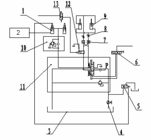
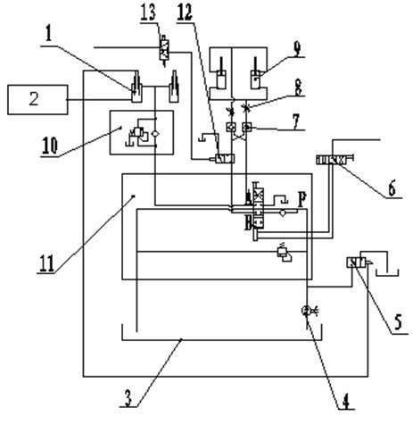
[0010] In conjunction with the accompanying drawings, the hydraulic circuit controlled by the sequence valve and the limit air valve in the present invention includes a single-acting hydraulic cylinder 1, a double multi-way valve (cylinder control / oil cylinder control) 2, a hydraulic oil tank 3, an oil pump 4, a stroke valve 5, Pneumatic control valve 6, hydraulic lock 7, two-way throttle valve 8, double-acting hydraulic cylinder 9, sequence valve 10, single multi-way valve (air cylinder control / oil cylinder control) 11, two-position three-way solenoid valve or two-position three-way air Control valve 12, limit air valve or travel switch 13, wherein hydraulic oil tank 3 and oil pump 4 are connected with low-pressure oil pipes, hydraulic oil tank 3 is installed in the spare space on the chassis, and is fixed on the chassis with brackets; oil pump 4 is connected with transmission shaft and The power take-off on the chassis is connected and fixed on the chassis with a bracket.
...
PUM
 Abstract
Description
Claims
Application Information
 - Generate Ideas
- Intellectual Property
- Life Sciences
- Materials
- Tech Scout
- Unparalleled Data Quality
- Higher Quality Content
- 60% Fewer Hallucinations
Browse by: Latest US Patents, China's latest patents, Technical Efficacy Thesaurus, Application Domain, Technology Topic, Popular Technical Reports.
© 2025 PatSnap. All rights reserved.Legal|Privacy policy|Modern Slavery Act Transparency Statement|Sitemap|About US| Contact US: help@patsnap.com