

Telescopic-swivel hydraulic cylinder
A technology of telescopic rotation and hydraulic cylinders, which is applied in the field of hydraulic cylinders, can solve the problems of complex structure and high cost of the overall hydraulic system, and achieve the effects of simple structure, reduced costs, and improved economic benefits
- Summary
- Abstract
- Description
- Claims
- Application Information
AI Technical Summary
Problems solved by technology
Method used
Image

Examples
Embodiment Construction
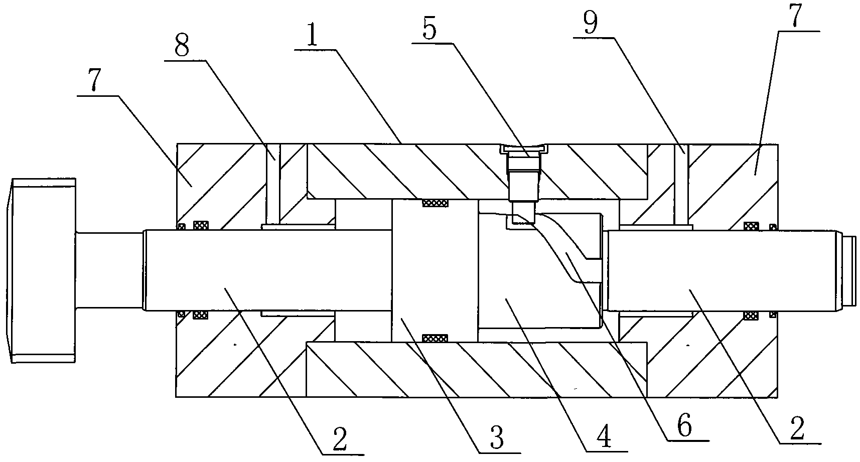
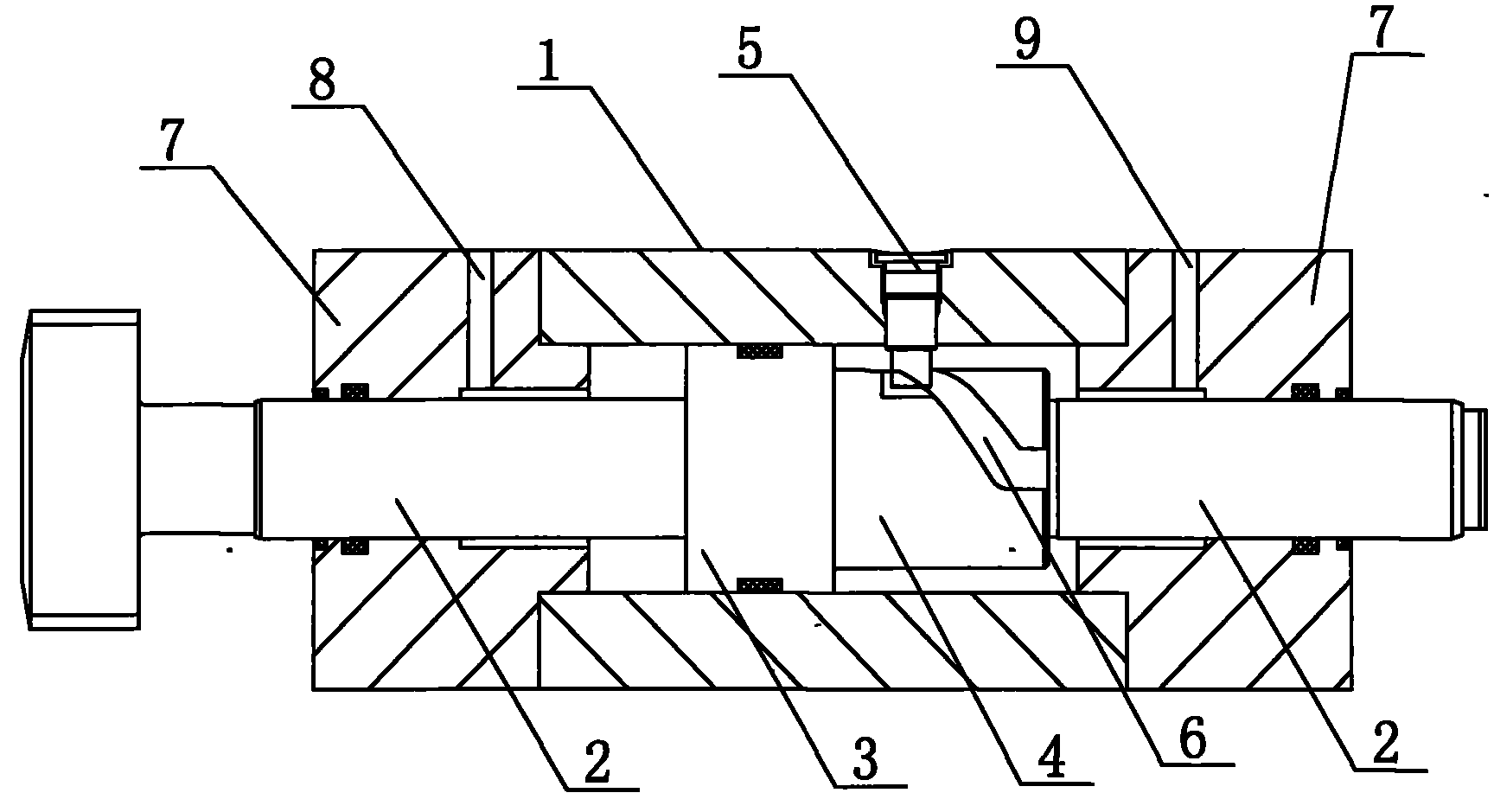
[0014] Please refer to figure 1 as shown, figure 1 It is a structural schematic diagram of the telescopic rotary hydraulic cylinder of the present invention. In this embodiment, the telescopic rotary hydraulic cylinder includes a piston 3, a piston rod 2, a cylinder body 1, and a first oil port 8 and a second oil port 9 communicating with the inner cavity of the cylinder body 1. The cylinder body 1 is fixed with a cylinder head 7 at both ends, the piston rod 2 passes through the piston 3 and runs through the entire cylinder body 1, and a spiral guide groove 6 is opened on the piston rod 2 on one side of the piston 3, and the spiral guide groove 6 is matched with the One end of the limit screw plug 5 is fixed on the inner wall of the cylinder body 1, and the other end of the limit screw plug 5 is clamped in the spiral guide groove 6. When the piston rod 2 moves linearly, it is guided by the limit screw plug 5 and the screw. The effect of the groove 6 can drive the piston rod ...
PUM
 Abstract
Description
Claims
Application Information