
Optical measuring system and method for coaxiality of extra-long-hole part

An optical measurement system and coaxiality technology, applied in the direction of measuring devices, optical devices, instruments, etc., can solve the problems that cannot meet the modern production and maintenance of aircraft, cannot meet the measurement of large passenger flap slat hole system, consume manpower and material resources, etc. problems, to achieve the effect of convenient measurement process, good reliability, improved efficiency and accuracy

Inactive Publication Date: 2012-01-18
NANJING UNIV OF AERONAUTICS & ASTRONAUTICS
View PDF8 Cites 49 Cited by
  • Summary
  • Abstract
  • Description
  • Claims
  • Application Information

AI Technical Summary

Problems solved by technology

[0005] In the domestic hole system coaxiality measurement method, the current method is generally for large-size hole system measurement, and in the measurement method for small-size hole system, the length of the measurement hole system is generally very small, no more than 100mm, Unable to meet the measurement of passenger flap slat hole system
At present, the measurement of the coaxiality of aircraft flaps and slats is based on the method of manual plug gauges, which not only consumes manpower and material resources, but also requires the operator to have rich practical experience, and the proportion of unqualified parts that pass the inspection is still high.
This can no longer meet the needs of modern aircraft production and maintenance, prolonging the production cycle and increasing manufacturing costs

Method used


Image

  • Optical measuring system and method for coaxiality of extra-long-hole part
  • Optical measuring system and method for coaxiality of extra-long-hole part
  • Optical measuring system and method for coaxiality of extra-long-hole part

Examples


Embodiment Construction

[0018] The optical measuring device for coaxiality of the super-long hole system of the present invention will be described below in conjunction with the accompanying drawings.

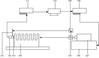
[0019] like figure 1 As shown, the ultra-long hole system coaxiality optical measuring device of the present invention comprises:

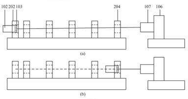
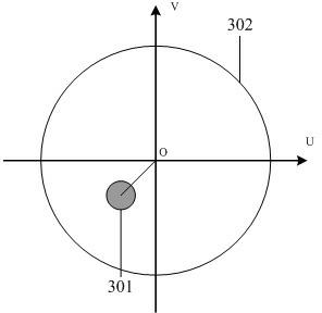
[0020] Orientation rod 101 is placed on the integrated measuring head, and the orientation rod is equipped with a photoelectric sensor. When the laser hits the photoelectric sensor, it indicates that the coordinate position of the PSD on the integrated measuring head has been adjusted, and the position information of the laser spot on the PSD can be collected;

[0021] Self-centering comprehensive measuring head 102, with three measuring claws, is driven by a precision screw, ratchet and motor. When measuring, the motor rotates and drives the three measuring claws to extend out at the same time to clamp the inner diameter of the hole. On the PSD where the probe is fixed...


PUM


Abstract

The invention relates to an optical measuring system and method for coaxiality of an extra-long-hole part, belonging to the technical field of coaxiality measurement. The measuring system comprises an oriented rod (101), a self-centering comprehensive measuring head (102), a position sensitive detector (PSD) (103), the extra-long-hole part (104), a spectroscope (105), a four-dimensional collimation platform (106), a laser transmitter (107), a motion control card (108), a reflecting mirror (109), a computer (110), a data acquisition card (111) and the like. During measurement, a laser collimation centerline is determined firstly according to the centers of a head hole and a tail hole and then the coaxiality value of the holes is obtained through a minimum zone method. The optical measuringsystem and method for the coaxiality of the extra-long-hole part has the advantages of high efficiency and high accuracy.

Description

[0001] technical field [0002] The invention relates to coaxiality detection technology, more specifically, a system and method for efficiently measuring the coaxiality of parts with super long holes by using technologies such as laser, PSD sensor and comprehensive measuring head. Background technique [0003] In the field of aerospace and weaponry, the hole system is used as a key component to transmit torque and output power, especially for fixed-wing aircraft, the rotation of its ailerons and flaps and slats is to achieve aircraft pitch, deflection, roll and other actions. guarantee. The holes on the flaps and slats of the aircraft belong to the ultra-long array hole system, the length can reach 3-5 meters, and the size of the holes is generally around Φ20mm. The characteristics of this type of hole are: the single hole diameter is small; the part size is super long; there is no measurement and installation reference. If there is a problem with the coaxiality of the ul...

Claims


Application Information

Patent Timeline
Patent Type & Authority Applications(China)
IPC IPC(8): G01B11/27
Inventor 陆永华赵转萍余厚云
Owner NANJING UNIV OF AERONAUTICS & ASTRONAUTICS
Learn More