
Geotechnical thermal response testing method

A technology of thermal response testing and rock soil, applied in the field of thermal response testing, can solve problems such as inaccuracy, large error, and inability to obtain thermal and physical parameters, and achieve the effect of reducing errors

Inactive Publication Date: 2012-01-18
江亚斌
View PDF3 Cites 10 Cited by
  • Summary
  • Abstract
  • Description
  • Claims
  • Application Information

AI Technical Summary

Problems solved by technology

Because voltage instability often occurs on the construction site, this method may be very inaccurate, and even the corresponding thermal and physical parameters cannot be obtained. If there is a power outage, the data cannot be analyzed, and because the test well has been thermally disturbed, it cannot be used in the short term. restart the test;
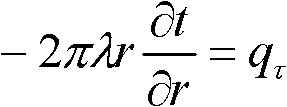
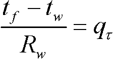
[0009] 2. The thermal resistance in the well is usually calculated by theoretical methods or semi-empirical formulas, not obtained through test data, and the error is large
[0010] 3. The heat capacity of the soil cannot be directly calculated. There are two common methods: a. According to the rock-soil properties of each depth measured in the geological survey report, check the heat capacity of these rock-soil layers respectively, and then weight the average; b. Use According to the linear heat source theory, after the thermal conductivity and thermal resistance in the well have been obtained, the heat capacity can be directly deduced by the formula. However, it has been mentioned above that the calculation of the thermal resistance has a large error, and the thermal capacity derived based on the thermal resistance with a large error The error is bound to be large

Method used


Image

  • Geotechnical thermal response testing method
  • Geotechnical thermal response testing method
  • Geotechnical thermal response testing method

Examples


Embodiment Construction

[0021] The following are specific examples of the present invention, but the present invention is not limited to these examples.

[0022] The thermal response testing device used in this geotechnical thermal response test method includes a liquid circulation loop connected in turn by a water pump, a heater, and an underground pipe. There is also a flow sensor on the circuit, and the heater is a heater with adjustable heating power, and a power sensor is arranged in the heater. The thermal response test device also includes an acquisition control system, a heater, a power sensor, a temperature sensor and a flow rate sensor. The sensors are all connected with the acquisition control system, and the acquisition control system can collect the data of each sensor and control the heater for heating.

[0023] The thermal response test method of the rock and soil is as follows: the actual temperature value of the buried pipe is tested by the temperature sensor, and there are two tempe...


PUM


Abstract

The invention provides a geotechnical thermal response testing method, which belongs to the technical field of ground source heat pumps and solves the problem of large errors of theoretical calculation results in the conventional geotechnical thermal response testing method. The method comprises the following steps of: testing an actual measurement temperature value of an underground pipe by using a temperature sensor; inputting changed heating power by controlling a heater through an acquisition control system; measuring an actual flow value by using a flow sensor; substituting the actual flow value and the heating power into a discretization equation of a linear heat source or column heat source model; changing a geotechnical thermal conductivity coefficient, a geotechnical heat capacity value and a well hole thermal resistance value, substituting into the discretization equation, and solving a pilot calculation temperature value of the underground pipe; and comparing the solved pilot calculation temperature value with the actual measurement temperature value, wherein the substituted geotechnical thermal conductivity coefficient, geotechnical thermal capacity value and well holethermal resistance value are the solved parameter values when the pilot calculation temperature value and the actual measurement temperature value have the minimum mean square deviation or the maximum correlation coefficient after repeated pilot calculation. By the method, data is acquired by testing under variable working conditions, so that the accuracy is improved.

Description

technical field [0001] The invention belongs to the technical field of ground source heat pumps and relates to a thermal response testing method. Background technique [0002] Ground source heat pump is a kind of heat resource that utilizes the shallow underground layer, also known as ground energy, including groundwater, soil or surface water, etc., and transfers low-temperature potential energy to high-temperature potential energy through a small amount of high-level energy such as electric energy, so as to achieve both High-efficiency energy-saving air-conditioning over-input system for heating and cooling. The ground source heat pump utilizes the characteristics of the stable temperature of ground energy throughout the year. In winter, the ground energy is used as the heat source for heat pump heating, that is, the heat energy in the ground energy that is higher than the ambient temperature is taken out to supply indoor heating. In summer, the ground energy is used as th...

Claims


Application Information

Patent Timeline
Patent Type & Authority Applications(China)
IPC IPC(8): G01N25/20
Inventor 江亚斌
Owner 江亚斌
Learn More