
Energy factor based ultrasonic guided wave detection method of debonding defect of bonding structure

A technology of ultrasonic guided wave and energy factor, which is applied in the direction of analyzing solids using sound wave/ultrasonic wave/infrasonic wave, which can solve the problems of low detection efficiency and inability to detect, and achieve fast detection speed, sensitive change of target characteristic value, and high detection efficiency Effect

Inactive Publication Date: 2012-01-18
PLA SECOND ARTILLERY ENGINEERING UNIVERSITY
View PDF0 Cites 9 Cited by
  • Summary
  • Abstract
  • Description
  • Claims
  • Application Information

AI Technical Summary

Problems solved by technology

Whether it is the ultrasonic penetration method or the pulse echo method, the detection process is "point-by-point" detection, that is, one detection signal corresponds to one point, so for large-area bonding structures, the detection efficiency is relatively low
In addition, both the ultrasonic penetration method and the pulse echo method require that the transducer must be in contact with or close to the measured area, and if the measured area is blocked by other obstacles, the detection cannot be performed

Method used


Image

  • Energy factor based ultrasonic guided wave detection method of debonding defect of bonding structure
  • Energy factor based ultrasonic guided wave detection method of debonding defect of bonding structure
  • Energy factor based ultrasonic guided wave detection method of debonding defect of bonding structure

Examples


Embodiment 1

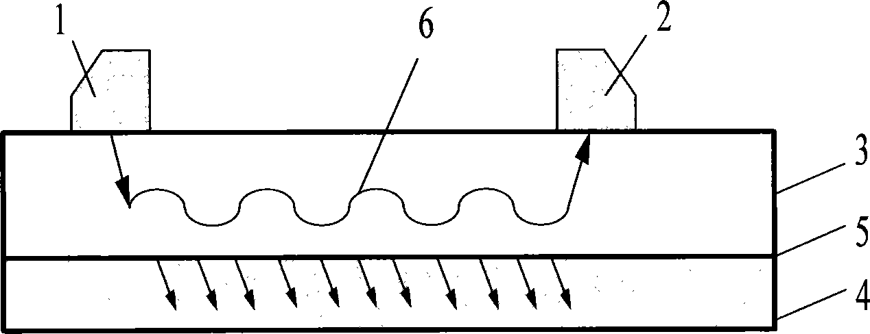
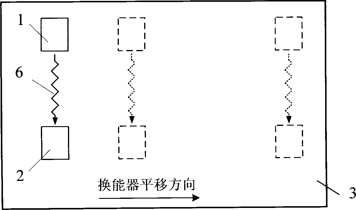
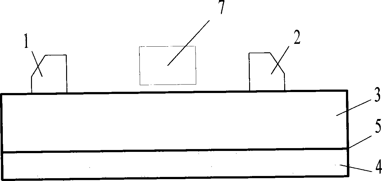
[0032] Such as figure 1 As shown, the sample to be tested in this embodiment is a bonded structure of glass fiber composite material plate and rubber, the size is 200mm×200mm, the upper medium is a composite material plate with a thickness of 5mm, and the lower medium is rubber with a thickness of 3mm. A circular debonding defect with a diameter of 30 mm was artificially prefabricated between the composite material and the rubber in the middle area of ​​the structure.

[0033] Step 1: Place two ultrasonic transducers with variable angles for transmitting and receiving on the composite material board, and the center frequency of the transducer is 0.5MHz; select the ultrasonic guided wave in the composite material board as S0 mode, and refer to the composite material board According to the dispersion curve, the velocity of the ultrasonic guided wave in this mode is about 4800m / s; the velocity of the longitudinal wave of the ultrasonic wave in the transducer is about 2700m / s; acc...

Embodiment 2

[0037] The above samples were compared for detection:

[0038] The sample was detected by the pulse echo detection method, the interface echo amplitude of the well-bonded area was 0.79, the interface echo amplitude of the debonding area was 1.1, and the target characteristic value of the debonding area (ie, the echo amplitude ) is 39.2% relative to the well-bonded area. However, with the method of the present invention, the change of the energy factor of the ultrasonic guided wave in the debonded area relative to the well-adhesive area is 49.3%. It can be seen that the method of the present invention is more sensitive to the change of the target eigenvalue than the pulse echo method, and it is easier to find the debonding defect.


PUM


Abstract

The invention relates to an energy factor based ultrasonic guided wave detection method of the debonding defect of a bonding structure, which is characterized in that: whether a region of a connecting line between a transmitter transducer and a receiver transducer has the debonding defect or not is judged according to the size of the energy factor of received ultrasonic guided waves. Compared with the prior art, the detection method has the advantages of quick detection speed, high efficiency and wide covering range of detection regions, and can realize the detection of unreachable parts of certain transducers; and compared with the traditional pulse echo method, the target feature value changes more sensitively and the debonding defect is more easily found.

Description

technical field [0001] The invention belongs to the technical field of non-destructive testing, and relates to an ultrasonic guided wave method for detecting debonding defects of bonding structures, in particular to an energy factor-based ultrasonic guiding wave detecting method for debonding defects of bonding structures. Background technique [0002] Adhesive structure is a common structural form, which has the advantages of light weight, high strength, and low cost, and is widely used in people's production and life. The quality of the bonding directly affects the performance and reliability of the bonded structure, and debonding is the most harmful type of defect in the bonded structure. It will significantly reduce the structural strength, cause structural failure, and even lead to catastrophic consequences. . Therefore, the detection of debonding defects in the production and use of bonded structures has attracted much attention. [0003] In the prior art prior to th...

Claims


Application Information

Patent Timeline
Patent Type & Authority Applications(China)
IPC IPC(8): G01N29/04
Inventor 强洪夫艾春安李剑王学仁刘新国
Owner PLA SECOND ARTILLERY ENGINEERING UNIVERSITY
Learn More