
Display screen visual angle regulating method and display device

An adjustment method and technology of display equipment, applied in the direction of TV, color TV, components of color TV, etc., can solve the problems of failure, cannot be excluded, increase the user's viewing angle, etc., to achieve the effect of improving visual experience and improving accuracy

Inactive Publication Date: 2012-01-18
HISENSE VISUAL TECH CO LTD
View PDF6 Cites 66 Cited by
  • Summary
  • Abstract
  • Description
  • Claims
  • Application Information

AI Technical Summary

Problems solved by technology

This solution does solve the user's troubles to a certain extent, but, just like the traditional hand-held remote control, the user must manually adjust the rotation angle of the TV main body according to his own viewing position, therefore, it does not allow the TV user to get a complete solution. The liberation of TV users still restrains the behavior of TV users to a large extent.
Moreover, it is obvious that this solution only solves the problem of increasing the user's viewing angle when the TV is installed on the base, and this method is completely ineffective when the TV is installed on the wall using pendants
If the pendant is also designed in the shape of a boomerang, it cannot be ruled out that the user hits the TV against the wall with excessive force when adjusting the viewing angle and damages the screen
So this solution has a big flaw

Method used


Image

  • Display screen visual angle regulating method and display device
  • Display screen visual angle regulating method and display device
  • Display screen visual angle regulating method and display device

Examples


Embodiment Construction

[0038] Specific embodiments of the present invention will be described in detail below in conjunction with the accompanying drawings.

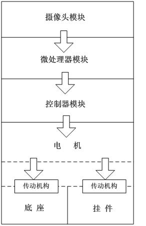
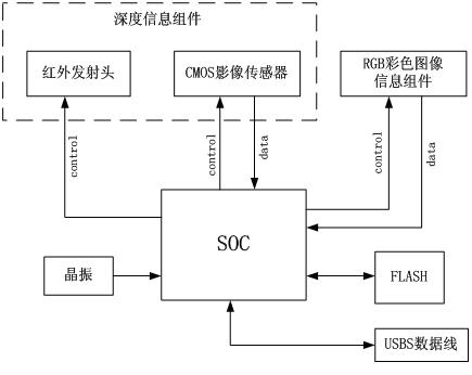
[0039] In this embodiment, a TV is used as a display device as an example, and the overall structure of the viewing angle adjustment system of the display screen is firstly introduced, as shown in figure 1 As shown, including camera module, microprocessor module and driver module. The drive module includes a controller module, a motor and a transmission mechanism driven by the motor. Wherein, the camera module and the microprocessor module can be built in the main body of the TV, and the driving module can be arranged inside the TV base or the pendant, and control the rotation of the TV display screen relative to the TV base or the pendant according to the driving signal output by the microprocessor module Or pan up and down. Of course, whether each module is built-in and where it is built-in in the TV set can be freely designed, and this em...


PUM


Abstract

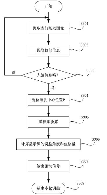
The invention discloses a display screen visual angle regulating method and a television. The method comprises the following steps: firstly, utilizing a camera module to obtain a two-dimensional image and depth information of a part in front of the display screen, and transmitting the two-dimensional image and depth information to a microprocessor module; utilizing the microprocessor module to extract a face information from the received two-dimensional image, and locating the central positions of pupils; and then working out an adjusting angle and / or an up-down displacement of the display screen according to the central positions of the pupils and the central position of the display screen, and driving the display screen to carry out the visual angle adjustment through a driving module. By the implementation of the display screen visual angle adjusting technology in the invention, the display device can automatically track user position so that the visual angle of the screen does not need to be regulated manually when a user uses the display device, thus the automatic regulation of the display screen visual angle is truly realized; and the visual angle regulation precision is improved, the user can watch a video program at the best visual angle from any position in the same room, and the visual experience of the user is greatly improved.

Description

technical field [0001] The present invention belongs to the technical field of display devices, and in particular relates to a method for adjusting the viewing angle of a display screen and a display device designed using the method for adjusting the viewing angle of a display screen. Background technique [0002] In modern life, television media is still the most popular, widest, fastest and most accepted carrier of information dissemination. No matter the current TV is installed or from the TV itself, it cannot guarantee that the user can watch TV at the best viewing angle at any time, which makes the user unable to watch the program in the most comfortable way, thereby affecting the user's life. visual feeling. [0003] For this problem, in the current peers, there is such a solution, which is to set a boomerang-shaped rotating part in the TV base, so that the main body of the TV can rotate left and right flexibly relative to the base, thereby expanding the viewing angle...

Claims


Application Information

Patent Timeline
IPC IPC(8): G05D3/12H04N5/44G06K9/52G06K9/00
Inventor 孙锦红杨伟蕾马亮
Owner HISENSE VISUAL TECH CO LTD
Learn More