Double-shaft solar automatic tracking power generation device and sensing probe thereof

A technology of sensing probe and power generation device, applied in the direction of using feedback control, etc., can solve the problems of complex control algorithm of power generation device controller, increase the complexity of production process, and high requirements for photoresistor photosensitivity, achieve strong geographical environment applicability, Realize the effect of automatic tracking and easy mass production

Inactive Publication Date: 2015-02-25
于银龙 +1
View PDF13 Cites 12 Cited by
  • Summary
  • Abstract
  • Description
  • Claims
  • Application Information

AI Technical Summary

Problems solved by technology

[0007] First, the solar tracking sensor detects the position of the sun by comparing the light levels of each photoresistor. In order to create environments with different light levels, it uses a more complex channel structure, which increases the complexity of the production process. And it has high photosensitive requirements for photoresistors, and it is easy to reduce reliability due to interference in complex lighting environments;
[0008] Second, the above-mentioned solar tracking sensor is applied in different geographical locations in various regions, and it is necessary to design cylinders of different heights, and to change the width of the left, right, upper and lower channels, and its environmental applicability is poor;
[0009] Third, after the four photoresistors of the above-mentioned solar tracking sensor are exposed to light, a series of calculations are required to obtain the driving signals of the azimuth rotation axis and the elevation angle rotation axis of the rotating mechanism. The control algorithm of the power generation device controller is relatively complicated.

Method used


Image

  • Double-shaft solar automatic tracking power generation device and sensing probe thereof
  • Double-shaft solar automatic tracking power generation device and sensing probe thereof
  • Double-shaft solar automatic tracking power generation device and sensing probe thereof

Examples


Embodiment Construction

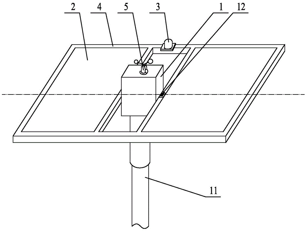
[0039] like image 3 As shown, the dual-axis solar automatic tracking power generation device of the present invention includes a dual-axis rotating mechanism 1, a solar panel 2 (for simplicity of description, the solar panels mentioned below all refer to solar panels), a transmission system for tracking the position of the sun Sensing probe 3, frame 4, the controller (not shown) that is used to control the rotation of biaxial rotating mechanism 1 and is provided with the anemometer 5 of maximum wind speed.

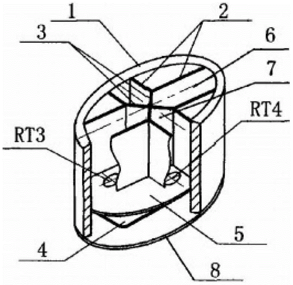
[0040] The sensing probe of the present invention includes a probe base 31, a cross-shaped partition 32, a light-shielding sheet 33, a light-reducing shell 34 for filtering out stray light, and four photosensitive elements D1-D4. Wherein, the probe base 31 is a disc body, the upper surface of the disc body is stepped, the high circular platform in the middle is the installation surface of the four photosensitive elements D1-D4, and the low circular surface is the installa...


PUM


Abstract

The invention discloses a double-shaft solar automatic tracking power generation device and a sensing probe thereof. The sensing probe comprises a probe base, four photosensitive components and a cross-shaped partition board, and is characterized in that the cross-shaped partition board is arranged on the probe base and divides the probe base into four independent areas in light isolation, and the four photosensitive components are installed in the four independent areas of the probe base respectively. The sensing probe further comprises a light shielding piece and a dimming shell used for filtering away diffusion light, the light shielding piece is arranged on the top of the cross-shaped partition board, the four photosensitive components are located in an orthographic projection area, of the light shielding piece, on the probe base, namely when sunlight vertically irradiates the probe base, the four photosensitive components are located in the shade, formed on the probe base, of the light shielding piece, the dimming shell covers the cross-shaped partition board and the light shielding piece, a gap is reserved between the dimming shell and the light shielding piece, and the side end face of the cross-shaped partition board is tightly attached to the inner wall of the dimming shell. By means of the double-shaft solar automatic tracking power generation device and the sensing probe, automatic tracking of the position of the sun can be achieved.

Description

technical field [0001] The invention relates to a solar tracking power generation device and a sun position sensor thereof, in particular to a dual-axis solar automatic tracking power generation device and a sensing probe thereof. Background technique [0002] The so-called solar automatic tracking power generation device is to make the solar panel face the sun at any time, so that the sunlight can be irradiated vertically on the solar panel as much as possible in real time, so as to obtain the highest solar energy collection efficiency. The position of the sun in the sky is often described by the solar altitude angle and solar azimuth angle, such as figure 1 As shown, it is a schematic diagram of the sun's apparent daily movement trajectory of a certain place O. From the figure, it can be seen that the sunshine time of this place O is about 5 o'clock to 18 o'clock, and the sun appears at the position from T5 to T18 relative to the place O. Z is the direct upward direction ...

Claims


Application Information

Patent Timeline
Patent Type & Authority Applications(China)
IPC IPC(8): G05D3/12
Inventor 于银龙
Owner 于银龙
Why Eureka
Try Eureka