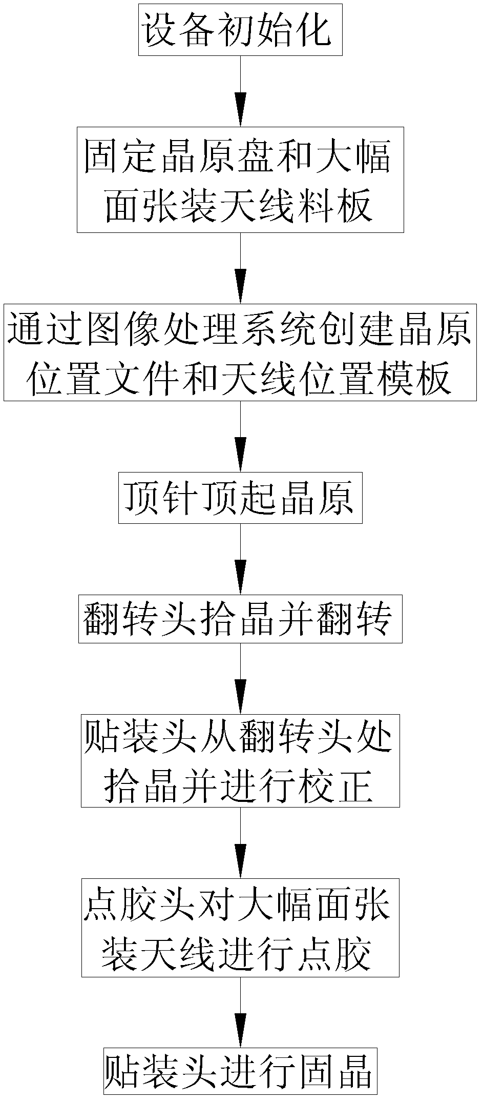
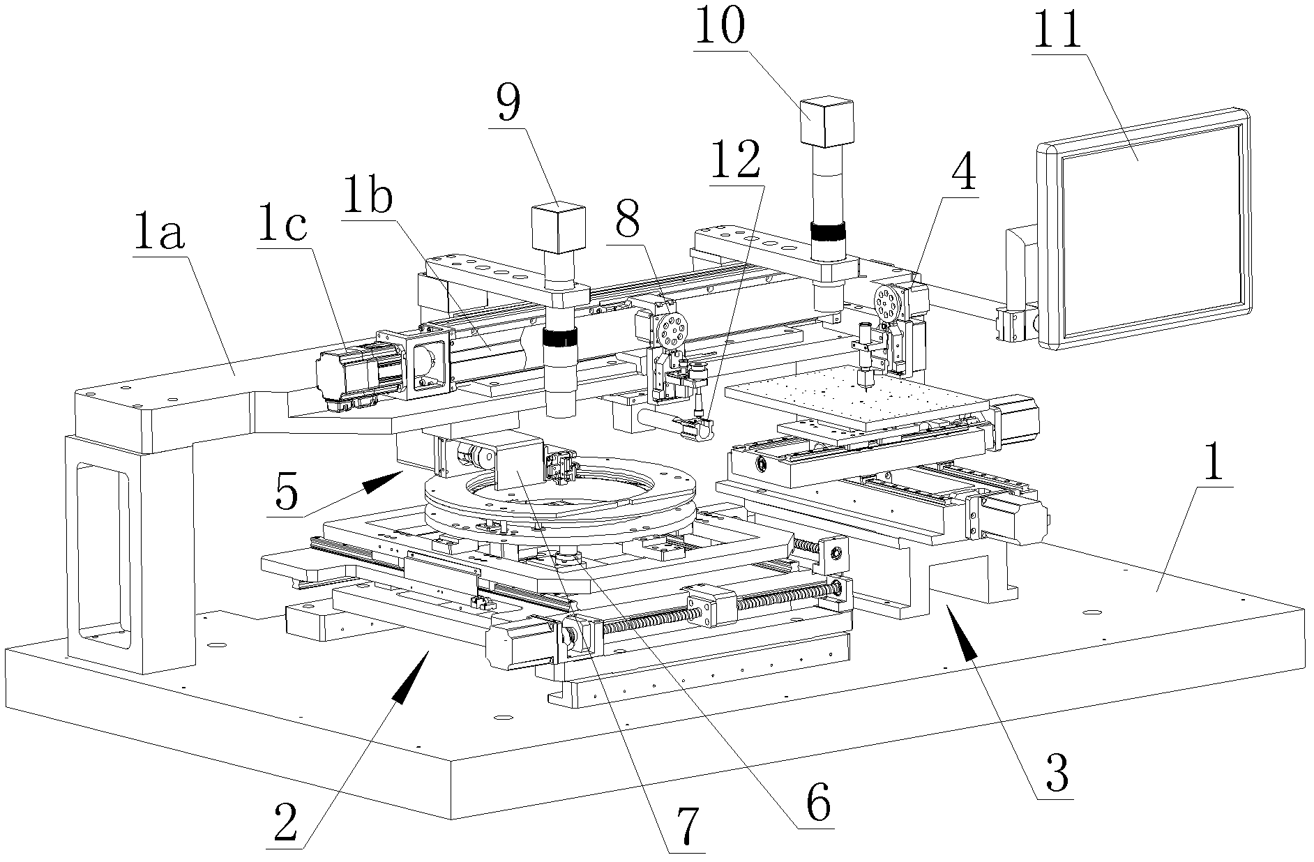
[0041] refer to figure 1 As shown, a kind of large-format sheet-packed RFID flip chip method of the present invention, the method comprises the following steps: (1) equipment initialization, each motion axis returns to the original point; The large-format sheet-mounted antenna sheets of multiple RFID antennas are placed on the wafer tray fixing module and the sheet-mounted antenna fixing module, and the positions of the chips and antennas are automatically positioned through the image recognition system, and then the wafer position files are created separately through the image recognition system and the antenna position template file; (3) The flipping head automatically flips to the wafer pick-up position, the thimble lifts up the chip, the flipping head sucks the wafer from the front and flips it, and the antenna material is installed in a large format while the flipping head picks up the crystal The board moves to the dispensing position for dispensing glue, and after the dispensing is completed, moves to the solid crystal position; (4) After the placement head picks up the chip from the flipping head, it first moves to the image recognition system, and the position of the chip is corrected by the image recognition system After the correction is completed, the placement head moves to the crystal-fixing position of the large-format antenna sheet, and fixes the chip on the glue; (5) Repeat steps (3) and (4) until the large-format antenna sheet is installed The antennas on the board are solidified; (6) Remove the large-format antenna sheet, put another large-format antenna sheet on the sheet-mounted antenna fixing module, and repeat (3) to (5) Actions.
[0042] refer to Figure 2 to Figure 17 As shown, a large-format RFID flip-chip device of the present invention includes a base 1, a support 1a is provided on the base 1, and a wafer fixing module 2 and a large-format wafer fixing module 2 are provided below the support 1a. The sheet-mounted antenna fixing module 3 is provided with a dispensing module 4 on the bracket 1a above the sheet-mounted antenna fixing module 3; an automatic chip flipping and mounting module is arranged between the wafer disk fixing module 2 and the sheet-mounting antenna fixing module 3 5. The chip flipping and mounting module 5 is composed of a chip ejecting module 6, a chip flipping module 7 and a chip mounting module 8 that cooperate with each other. The chip ejecting module 6 is set on the wafer on the wafer tray fixing module 2. Below the disk; the chip flipping module 7 is fixed on the support 1a, and the chip mounting module 8 is movably arranged on the support 1a, which is specifically provided with a screw 1b along the length direction on the support 1a, and one end of the screw 1b is connected to There is a horizontal servo motor 1c, and the chip mounting module 8 is threadedly connected to the screw rod 1b; the horizontal servo motor 1c, the wafer disk fixing module 2, the Zhangtian Zhang fixing module 3, the glue dispensing module 4, and the chip ejection module 6. The chip flipping module 7 and the chip mounting module 8 are respectively circuit-connected with a control unit; further, in order to improve the accuracy and automation of the equipment, a pick-up camera 9 and a die-bonding camera 10 are respectively provided on the support 1a. The crystal camera 9 is opposite to the chip ejection module 6, and the crystal-fixing camera 10 is opposite to the antenna fixing module 3; the crystal-picking camera 9 and the crystal-bonding camera 10 are connected to the control unit circuit respectively, and the control unit circuit is connected to a display screen 11, and the pick-up camera 9 and the crystal-fixing camera 10 are connected to the control unit circuit respectively, and the control unit circuit is connected to a display screen 11, and Both the crystal camera 9 and the solid crystal camera 10 are connected to the display screen 11 circuit, through the display screen 11, the working conditions of each part of the placement machine can be viewed intuitively and in real time; A correction camera 12 is provided on the bracket 1a between, and the correction camera 12 is opposite to the chip mounting module 8, and the correction camera 12 is electrically connected to the control unit; in this embodiment,
[0043] The chip ejection module 6 is composed of a support base 6a, a thimble mechanism arranged on the support base 6a, and a lifting drive device 6b arranged on the support base 6a below the thimble mechanism; the thimble mechanism includes a thimble cylinder 6c arranged on the support base 6a , the thimble guide cylinder 6d sleeved in the thimble cylinder 6c, the thimble seat 6e provided in the thimble cylinder 6c, the thimble 6f provided on the thimble seat 6e, the external thread ring 6g provided at the upper end of the thimble cylinder 6c, and the external thread The first thimble cap 6h that is threaded to the ring 6g, the positioning adjustment ring 6i that is threaded to the external threaded ring 6g below the first thimble cap 6h, and the lifting guide rod 6j that is arranged at the bottom of the thimble seat 6e; the external threaded ring 3 and the The thimble cylinder 2a is an integral structure, and the top of the first thimble cap 6h is provided with a through hole 6k compatible with the thimble 6f; the top of the first thimble cap 6h on the periphery of the through hole 6k is distributed with an air suction hole 6l, and the top of the thimble The side wall of the guide cylinder 6d is provided with an air extraction hole 6m connected to the external vacuum equipment pipeline, and the air extraction hole 6m communicates with the air suction hole 6l through the cavity formed between the thimble cylinder 6c and the first thimble cap 6h; the lifting drive device 6b It includes a motor 6n horizontally arranged on the support base 6a and an eccentric wheel 6o fixed on the power output shaft of the motor 6n. The lower end of the lifting guide rod 6j passes through the thimble cylinder 6c and the support base 6a is in contact with the eccentric wheel 6o; Further, a guide post 6p and a guide lift block 6q are provided at the bottom of the support base 6a, one end near end of the guide lift block 6q is movably sleeved on the guide post 6p, and the other end near end of the guide lift block 6q is provided with The inner threaded through hole is connected with an adjusting nut 6r, the upper end of the adjusting nut 6r is in contact with the bottom of the lifting guide rod 6j, the bottom of the adjusting nut 6r is in contact with the eccentric wheel 6o; the bottom of the supporting base 6a is in contact with the guide The outer periphery of the lifting guide rod 6j between the tops of the lifting block 6q is sleeved with a spring pad 6s and a return spring 6t from top to bottom. At the same time, in order to improve the precision of the thimble 6f, the thimble mechanism also includes a thimble clamping block 6u arranged on the thimble seat 6e on the periphery of the thimble 6f and a second thimble cap 6v arranged on the periphery of the thimble clamping block 6u; the thimble clamping block 6u It is sandwiched between the second thimble cap 6v and the thimble seat 6e.
[0044] The chip flipping module 7 is mainly composed of a flipping support 7a fixed on the support 1a, a flipping motor 7b horizontally arranged on the flipping support 7a, a rotating shaft 7c movably arranged on the flipping shaft 7a, and an outer end of the rotating shaft 7c. The rotary block 7d is composed of the wafer suction nozzle 7e arranged on the rotary block 7d; the wafer suction nozzle 7e corresponds to the thimble 6f, and the inner end of the rotary shaft 7c is linked with the turning motor 7b through a transmission belt; the wafer The suction nozzle 7e is respectively connected to an external compressed air source and a vacuum pump through pipelines, and a solenoid valve is provided on the pipeline between the external compressed air source, the vacuum pump and the wafer suction nozzle 7e, and the solenoid valve is connected to the control unit circuit.
[0045] The chip mounting module 8 is mainly composed of a mounting seat 8a, a mounting motor 8b arranged on the top of the mounting seat 8a, a mounting eccentric wheel 8c fixedly connected to the power output shaft of the mounting motor 8b, and a mounting eccentric wheel 8c arranged at the bottom of the mounting seat 8a. The sliding rail 8d, the sliding block 8e that is movably arranged on the sliding rail 8d, the mounting fixed block 8f fixedly connected with the sliding block 8e, and the mounting suction nozzle 8g arranged on the mounting fixed block 8f are composed; the sliding One end of the block 8e along the vertical direction is in contact with the placement eccentric wheel 8c, and a return spring 8h is arranged between the other end of the slider 8e and the placement seat 8a along the vertical direction; the placement suction nozzle 8g is respectively compressed with the outside through the pipeline. The air source is connected to the vacuum pump, and a solenoid valve is provided on the pipeline between the external compressed air source and the vacuum pump and the mounting nozzle 8g, and the solenoid valve is connected to the control unit circuit; the external compressed air source is generated by an air compressor; Further, a horizontal driving motor 8i is provided on the mounting and fixing block 8f, and the horizontal driving motor 8i is linked with the mounting nozzle 8g through a transmission belt, and the horizontal driving motor 8i is connected to the control unit circuit. The power output shaft of the mounting motor 8b is also connected with a flagpole 8j for controlling the rotation angle of the mounting motor 8b, and an inductor 8k is arranged on the mounting seat 8a on the side of the flagpole; the flagpole 8j cooperates with the inductor 8k to control the motor. Rotating this structure is applicable to the lifting motor 4b of the dispensing module 4 and the motor 6n of the chip ejection module 6 .
[0046] A horizontal drive motor 8i is provided on the mount fixing block 8f, and the horizontal drive motor 8i is linked with the mounting suction nozzle 8g through a transmission belt, and the horizontal drive motor 8i is connected with the control unit circuit.
[0047] The wafer disk fixing module 2 is composed of a first horizontal two-dimensional adjustment seat 2a and a wafer disk fixing frame 2b movably arranged on the first horizontal two-dimensional adjustment seat 2a, and the wafer disk is fixed on the wafer disk fixing frame 2b; The driving device of the first horizontal two-dimensional adjustment seat 2a is connected with the control unit circuit.
[0048] The fixed antenna module 3 is composed of a second horizontal two-dimensional adjustment seat 3a and a large-format antenna fixed platform 3b that is movably arranged on the second horizontal two-dimensional adjustment seat 3a; the large-format antenna fixed platform 3b There are air holes 3c distributed on it, and an air channel 3d communicating with each air hole 3c is provided along the horizontal direction in the large-format antenna fixing platform 3b. The air channel 3d is connected with an external compressed air source and a vacuum pump pipeline, and the external compressed air A solenoid valve is provided on the pipeline between the source and the vacuum pump and the air channel 3d, and the solenoid valve is connected to the circuit of the control unit; the driving device of the second horizontal two-dimensional adjustment seat 3a is connected to the circuit of the control unit.
[0049] The structures of the first horizontal two-dimensional adjustment seat 2a and the second horizontal two-dimensional adjustment seat 3a are existing conventional structures. Considering the precision requirements of the patch, the screw rod is used to cooperate with the servo motor to achieve high-precision and fully automatic movement. , each servo motor moves through the control unit control.
[0050] The dispensing module 4 mainly consists of a dispensing support 4a fixed on the support 1a, a lifting motor 4b arranged on the upper part of the dispensing support 4a, a dispensing eccentric wheel 4c fixedly connected with the lifting motor 4b, and a dispensing eccentric wheel 4c fixedly connected to the dispensing support 4a. Dispensing slide rail 4d, the dispensing slider 4e that is movably arranged on the dispensing slide rail 4d, the dispensing seat 4f that is fixedly connected with the dispensing slider 4e, the glue storage cylinder 4g that is arranged on the dispensing seat 4f and the setting The dispensing head 4h at the lower end of the glue storage cylinder 4g is composed of; one end of the dispensing slider 4e in the vertical direction is in contact with the dispensing eccentric wheel 4c, and the other end of the dispensing slider 4e is in contact with the dispensing bracket 4a There is a dispensing return spring 4i in the vertical direction; the rubber storage cylinder 4g is connected to an external compressed air source through a pipeline, and a solenoid valve is installed on the pipeline between the external compressed air source and the rubber storage cylinder 4g, and the solenoid valve and the control unit circuit connection.
[0051] During specific work, the equipment is initialized, and all moving parts return to the original point, and the display screen 11 will display the homing state; On the large-format antenna fixing table 3b, the wafer position file and the antenna position template are respectively created by the pick-up camera 9 and the die-bonding camera 10; The nozzle 7e is turned over to the position opposite to the thimble 6f, the first horizontal two-dimensional adjustment seat 2a cooperates with the pick-up camera 9 to position the wafer, then the thimble 6f lifts the wafer, and at the same time connects the vacuum pump through the suction hole 61 around the through hole 6k Inhale to fix the wafer around the lifted wafer; after the wafer is lifted, the wafer suction nozzle 7e is connected to the vacuum pump to inhale, suck the wafer tightly from the front and turn it over 180 degrees, just in line with the chip mounting module 8 At this time, the wafer suction nozzle 7e is controlled by the control unit and connected to the air compressor for air injection. At the same time, the mounting suction nozzle 8g is controlled by the control unit and connected to the vacuum pump for suction, and the wafer is sucked tightly before the placement On the suction nozzle 8g, and then move to the bottom of the correction camera 12, through the image recognition system, the image captured by the correction camera 12 is matched with the pre-stored standard image, and then the horizontal drive motor 8i is controlled by the control unit to drive the placement suction nozzle 8g to rotate Rotate the wafer to the normal position at the proper position. After the correction is completed, the chip mounting module 8 is driven to continue moving to the die-bonding position through the screw rod 1b on the bracket 1a; while the chip flipping module 7 picks up the crystal, the die-bonding camera 10 Under the control of the control unit, the antenna is automatically found and matched. After matching, under the control of the control unit, the second horizontal two-dimensional adjustment seat 3a drives the large-format antenna sheet to move to the dispensing position for dispensing. After the completion, the second horizontal two-dimensional adjustment seat 3a is shifted back to the bottom of the die-bonding camera 10 according to the control unit, that is, the dispensing position; therefore, the chip mounting module 8 picks up the wafer from the chip flipping module 7 and corrects it. , without waiting, you can directly move to the die bonding position for die bonding. When bonding the die, connect the air compressor to blow air through the mounting nozzle 8g, and fix the wafer on the glue to complete the chip mounting once. Then the wafer fixing module 2, the antenna fixing module 3, the dispensing module 4, the chip ejection module 6, the chip flipping module 7, the chip mounting module 8, the crystal picking camera 9, the solid crystal camera 10, the display screen 11 and Calibrate the camera 12 and repeat the above steps respectively until the antennas on the large-format antenna material boards complete the crystal bonding, that is, complete the flip chip work of the antenna material boards one by one, then remove the material boards and replace them with new ones. For the material board to be mounted, the above-mentioned equipment is controlled by the control unit to continue to repeat the above-mentioned actions.