Power divider, electronic device, radio frequency front-end device and power dividing method

A power divider and electronic device technology, applied in the field of communication, can solve the problems of increasing the manufacturing cost of the power divider, difficult integration of single-layer microstrip line subsystems, and cost barriers.

Inactive Publication Date: 2012-01-18
北京瑞德艾迪科技有限公司
View PDF5 Cites 6 Cited by
  • Summary
  • Abstract
  • Description
  • Claims
  • Application Information

AI Technical Summary

Problems solved by technology

In the actual radio frequency circuit or system, the original single-section Wilkinson power divider has certain limitations in the working bandwidth and cannot meet the requirements of the 3.1-10.6GHz ultra-wideband (UWB) system
[0003] In order to solve such problems, in 2007, Dr. Abbosh of Australia proposed the design of an ultra-wideband power divider using a multi-layer coupled line structure, but its structure is complex, and it is difficult to design and manufacture. cost barrier
In 2010, Dr. Song and Dr. Xue fro

Method used


Image

  • Power divider, electronic device, radio frequency front-end device and power dividing method
  • Power divider, electronic device, radio frequency front-end device and power dividing method
  • Power divider, electronic device, radio frequency front-end device and power dividing method

Examples


Embodiment Construction

[0038] The technical solutions of the various embodiments of the present invention will be clearly and completely described below in conjunction with the accompanying drawings. Apparently, the described embodiments are only some of the embodiments of the present invention, not all of them. Based on the embodiments of the present invention, all other embodiments obtained by persons of ordinary skill in the art without making creative efforts belong to the protection scope of the present invention.

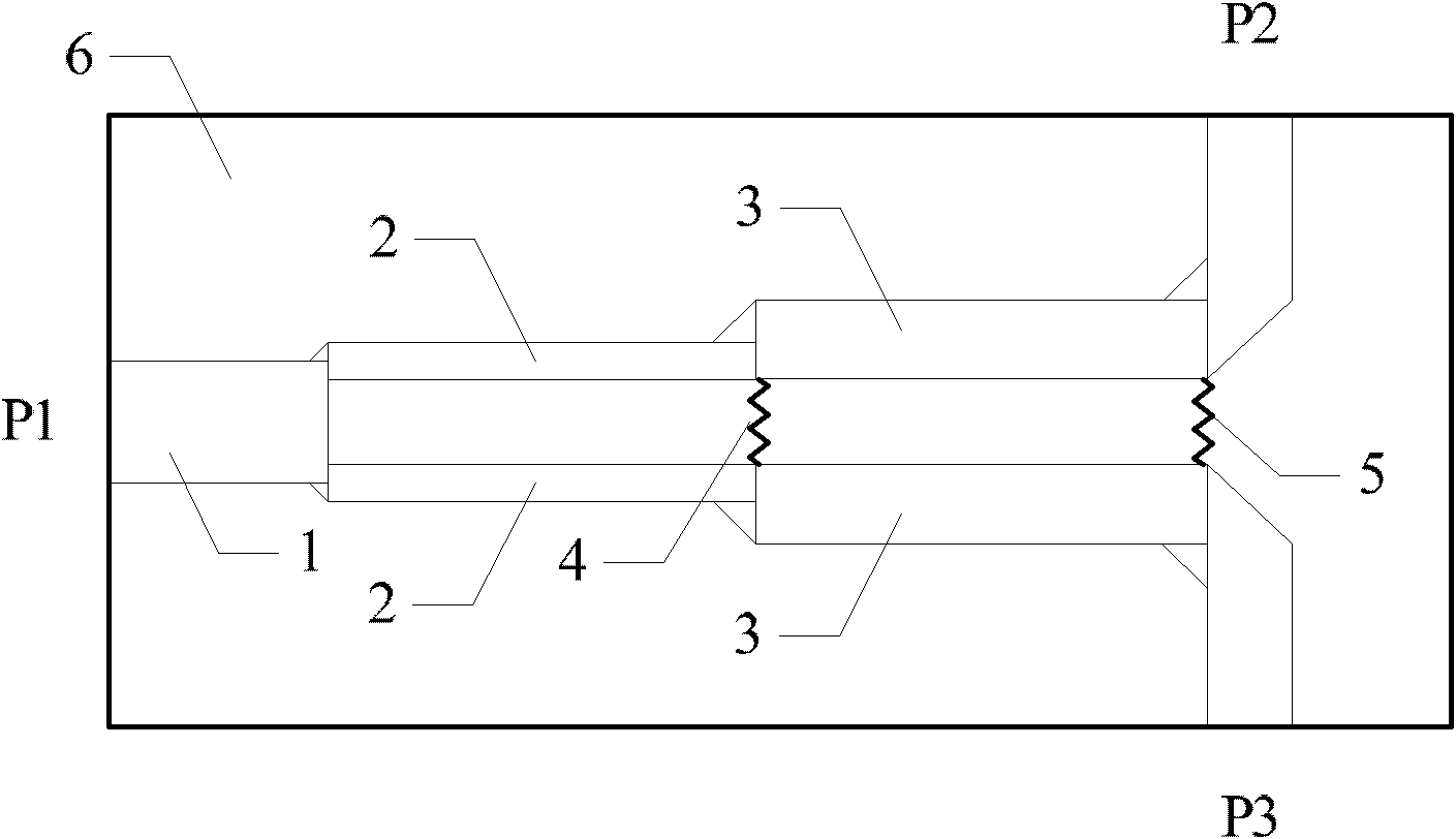
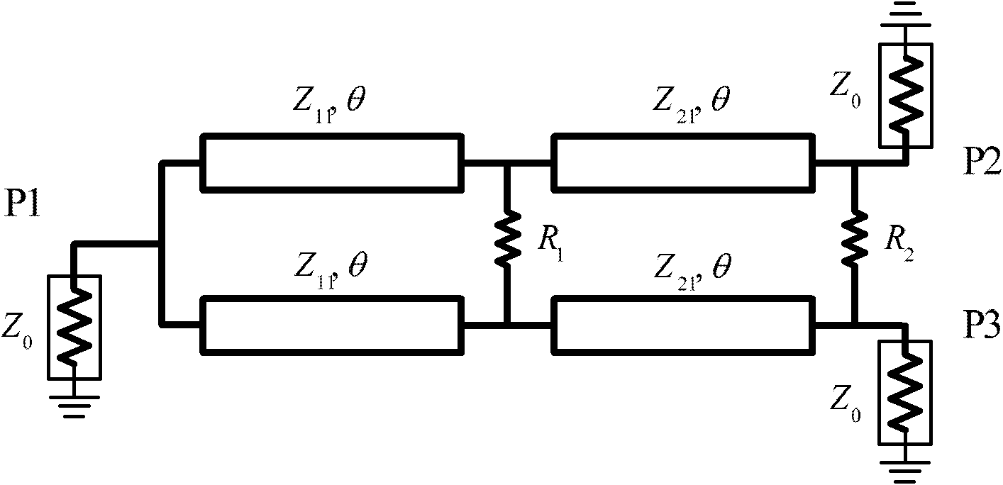
[0039] The invention provides a power splitter, comprising:

[0040] an input port, and first and second output ports;

[0041] From the input port to the first and second output ports, there are at least two segments with sequentially decreasing characteristic impedances connected in series, and each of the segments includes a parallel transmission line;

[0042] Each parallel transmission line in each segment is connected at its end on the side of the first and second output port...


PUM


Abstract

The invention relates to the field of communication, in particular to a power divider, an electronic device, a radio frequency front-end device and a power dividing method. The power divider comprises an input port (P1), a first output port (P2) and a second output port (P3), wherein at least two segments of which the characteristic impedances decrease in sequence are connected in series between the input port (P1) and the first and second output ports (P2, P3); each segment comprises transmission lines which are connected in parallel; each parallel transmission line in every segment is connected through a concentrated resistor at the tail end of each segment which is positioned on one side of the first output port (P2) and one side of the second output port (P3); and the resistance of each concentrated resistor increases in sequence from the input port (P1) to the first and second output ports (P2,P3). Due to the adoption of the power divider, the electronic device, the radio frequency device and the power dividing method, ultra-wideband equal power dividing can be realized in a planar circuit mode.

Description

technical field [0001] The invention belongs to the technical field of communication, and in particular relates to a power distributor, an electronic device, a radio frequency front-end device and a power distribution method. Background technique [0002] Power dividers have important applications in high-gain antenna arrays, high-efficiency Doherty power amplifiers, and broadband balanced amplifiers. In actual radio frequency circuits or systems, the original single-section Wilkinson power divider has certain limitations in operating bandwidth and cannot meet the requirements of 3.1-10.6GHz ultra-wideband (UWB) systems. [0003] In order to solve such problems, in 2007, Dr. Abbosh of Australia proposed the design of an ultra-wideband power divider using a multi-layer coupled line structure, but its structure is complex, and it is difficult to design and manufacture. cost barrier. In 2010, Dr. Song and Dr. Xue from Hong Kong proposed to use multi-layer slot lines to realiz...

Claims


Application Information

Patent Timeline
IPC IPC(8): H01P5/12H01P5/16
Inventor 吴永乐
Owner 北京瑞德艾迪科技有限公司
Why Eureka
Try Eureka