
Control system for stereo video camera

A device control, stereo camera technology, applied in stereo systems, image communication, electrical components, etc., can solve the problems of low relative position accuracy, difficult to use correction, difficult to correct in real time, etc.

Active Publication Date: 2012-01-18
比比威株式会社
View PDF9 Cites 14 Cited by
  • Summary
  • Abstract
  • Description
  • Claims
  • Application Information

AI Technical Summary

Problems solved by technology

[0005] However, since the methods described in Patent Documents 1 and 2 all measure or set the relative positions of the two cameras in advance, and then correct the deviation between the actual positions of the cameras and the measured or set values, the amount of calculation increases. Large, and difficult to implement real-time correction
In addition, this type of method also has the disadvantages of low accuracy of the calculated relative position and difficulty in correcting the deviation of the rotation angle around the visual axis of the two eyes

Method used


Image

  • Control system for stereo video camera
  • Control system for stereo video camera
  • Control system for stereo video camera

Examples


Embodiment Construction

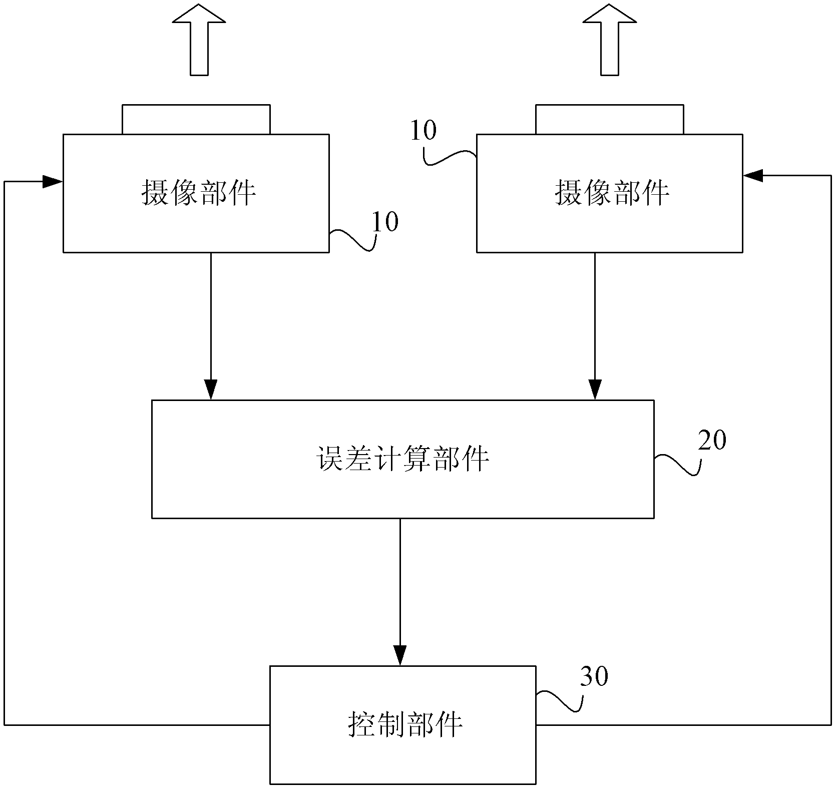
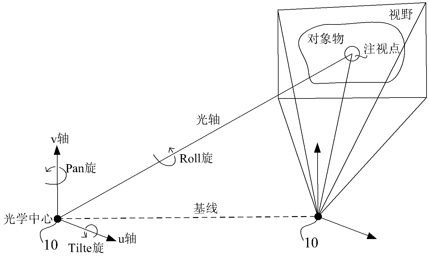
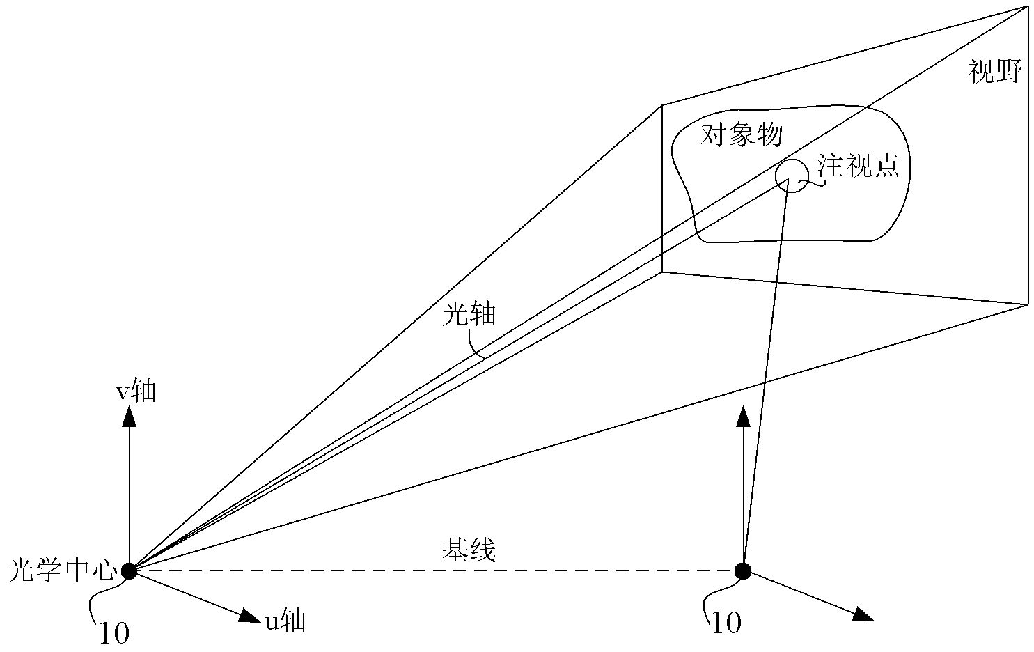
[0023] The following will combine Figure 1 to Figure 6 The control system of the stereo camera device of the present invention will be further described in detail.

[0024] figure 1 Shown is a schematic block diagram of the control system of the stereo camera device of the present invention. like figure 1 As shown, the stereo camera control system of the present invention includes two camera components 10 , an error calculation component 20 and a control component 30 .

[0025] The imaging component 10 has at least one controllable digital or analog degree of freedom for any parameter in Yaw, Pitch, Roll and zoom factor, and continuous imaging can be realized through the imaging elements it contains; wherein, the The digital degree of freedom refers to the several degrees of freedom that the imaging component has through the processing of rotation, parallel movement, and deformation correction of the continuous images obtained by shooting, although the imaging component it...


PUM


Abstract

The invention provides a control system for a stereo video camera. The control system can obtain stereo images with stereo visual effects even under the condition of unknown relative position relationship between two shooting parts. The control system for the stereo video camera comprises the two shooting parts, an error computing part and a control part, wherein the two shooting parts at least have one controllable digital or analogue degree of freedom for any parameter of Yaw, Pitch, Roll and a zoom rate, and can shoot continuous images by own shooting elements; the error computing part computes a rotating error and a zoom error between the shooting parts by comparing each image shot by the two shooting parts with a preset standard convergence model of each shooting part; and the control part controls the rotating angle and zoom rate of each shooting part by utilizing the rotating error and the zoom error computed by the error computing part.

Description

technical field [0001] The invention relates to a control system of a stereo camera device, in particular to a control system of a stereo camera device capable of correcting the position deviation of two camera components of the stereo camera device. Background technique [0002] A stereo camera device is a device that obtains a stereoscopic image by using two cameras placed on the left and right sides, respectively. In order to obtain a stereoscopic image in a conventional stereo camera device, the relative positions and relative postures of the two cameras are fixed. In order to improve the stereo vision function, a stereo camera device with multi-degree-of-freedom active cameras with the characteristics of convergent motion, variable baseline length, and variable focus has been developed. [0003] A relative positional misalignment between the two cameras prevents stereoscopic imagery from being generated. In order to eliminate the bias, various bias correction methods ...

Claims


Application Information

Patent Timeline
IPC IPC(8): H04N13/00
Inventor 张晓林甄梓宁
Owner 比比威株式会社
Learn More