Jet soldering device and soldering method

A brazing and jetting technology, which is applied in the direction of tin feeding device, welding equipment, printed circuit assembly of electrical components, etc., can solve the problem of molten solder 2 residues, etc., and achieve the effect of reducing bridging phenomenon

Inactive Publication Date: 2012-01-18
PANASONIC CORP
View PDF7 Cites 11 Cited by
  • Summary
  • Abstract
  • Description
  • Claims
  • Application Information

AI Technical Summary

Problems solved by technology

[0010] But if carry out drag welding with existing jet soldering device, then because the surface tension of molten solder 2 is bigger, the molten solder 2 that may be attached to the soldering position is also drawn after the soldering position passes jet nozzle 6 tops. Pull, so that the excess molten solder 2 remains in the state of drooping on the soldered part
The excess molten solder 2 left in this way causes soldering failures such as the so-called "bridging phenomenon" and "icicle phenomenon".

Method used


Image

  • Jet soldering device and soldering method
  • Jet soldering device and soldering method
  • Jet soldering device and soldering method

Examples


Embodiment Construction

[0049] Hereinafter, an embodiment of a jet brazing device and a brazing method according to the present invention will be described with reference to the drawings. However, the same reference numerals are assigned to the previously described elements, and descriptions thereof are appropriately omitted. Of course, the present invention is not limited to the embodiments described below.

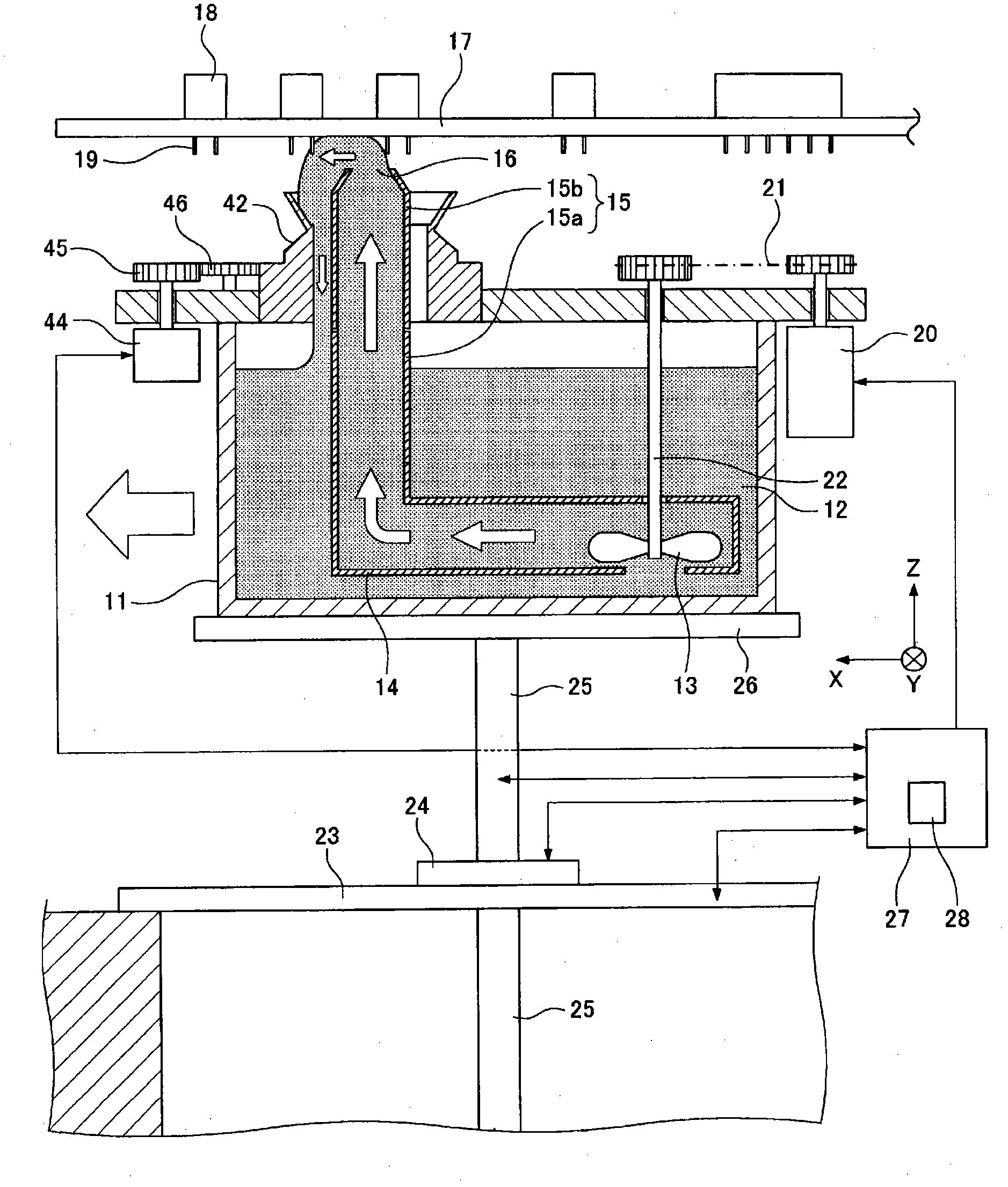
[0050] figure 1 It is a figure which shows the outline of one structural example of the jet soldering apparatus which concerns on embodiment of this invention. In this embodiment, the object to be soldered is a printed circuit board with through holes, and the soldered component to be soldered to the object to be soldered is an electronic component with leads. In addition, the objects to be soldered and the components to be soldered are not limited to printed circuit boards and electronic components.

[0051] Such as figure 1 As shown, the solder tank 11 contains molten solder 12 . By he...


PUM


Abstract

Provided is a jet soldering device with which it is possible to reduce problems associated with soldering such as bridging and protrusion formation. The disclosed jet soldering device is characterized by having: a solder bath (11) that stores melted solder; a jet nozzle (15) that comprises an end surface from which the melted solder is ejected, a cutout (30) provided in the aforementioned end surface, and a recovery wall (32) provided in the aforementioned end surface; a solder feeding mechanism (13, 20, 21, 22) that feeds the melted solder stored in the solder bath (11) to the jet nozzle (15); a tank driving mechanism (23, 24, 25, 26) that moves the solder bath (11); a solder receiving wall (42) that surrounds the jet nozzle (15) with a prescribed space therebetween and is connected to the jet nozzle (15); and a rotating mechanism (44, 45, 46) that transmits a drive force from the outside of the solder receiving wall (42) and rotates the solder receiving wall (42) and the adhesion nozzle (15).

Description

technical field [0001] The present invention relates to a jet brazing device and a brazing method for brazing a brazing component to a brazing object by bringing molten solder into local contact with the brazing object. Background technique [0002] Hereinafter, a conventional jet brazing device will be described with reference to the drawings. Figure 12 It is a figure which shows the outline of the structure of the conventional jet brazing apparatus. [0003] Such as Figure 12 As shown, the solder tank 1 contains molten solder 2 . The solder in the solder tank 1 can be melted by heating the solder tank 1 . Moreover, by controlling the temperature at which the solder tank 1 is heated, the molten solder 2 in the solder tank 1 can be kept at a constant temperature. [0004] A propeller 3 and a solder supply path 4 are provided in the solder tank 1 . The propeller 3 is arranged at one end of the solder supply path 4 . The molten solder 2 is pressure-fed inside the solder ...

Claims


Application Information

Patent Timeline
Patent Type & Authority Applications(China)
IPC IPC(8): H05K3/34B23K1/00B23K1/08B23K101/42
CPCB23K3/0653H05K3/3447H05K2203/0746H05K3/3468
Inventor 三村敏则山内大吉野信治
Owner PANASONIC CORP
Why Eureka
Try Eureka