Wiring panel welding tooling

A technology for welding tooling and wiring panels, applied in the field of tooling and fixtures, can solve the problems of short service life, large deviation of wiring panel structure and size, deformation of welding parts, etc., to prevent deformation, reduce defective rate, and ensure the effect of structure size

Inactive Publication Date: 2012-01-25
CHONGQING BEIBEI DISTRICT FENGHUO MACHINERY MFG
View PDF4 Cites 9 Cited by
  • Summary
  • Abstract
  • Description
  • Claims
  • Application Information

AI Technical Summary

Problems solved by technology

[0003] The junction panel is composed of a panel body with a concave plate, a one-way socket box and a DC junction box. The one-way socket box and the DC junction box are welded to the concave part of the wiring panel, and the one-way socket box is used to accommodate and install the socket. , the DC junction box is used to accommodate and install the wiring module, and in order to make the structure of the socket and the wiring module more compact, generally a small gap is left between the interior of the single-phase socket box and the DC junction box and the corresponding installation equipment, In the prior art, the welding of the wiring panel usually relies on the experience of the operator to ensure the shape and position error. First, the spot welding is positioned, and then the overall welding is performed. Not only is the positioning inaccurate, but also the high temperature generated during the welding process will deform the welded parts. The size deviation of the wiring panel after welding is relatively large, which is not conducive to the installation of other equipment. It will generate internal stress on the installation parts, and the service life is short. However, those severely deformed by high temperature will become unqualified products, resulting in waste of materials and costs.

Method used


Image

  • Wiring panel welding tooling
  • Wiring panel welding tooling
  • Wiring panel welding tooling

Examples


Embodiment Construction

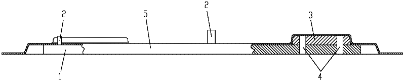
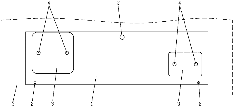
[0013] figure 1 It is the front view of the present invention, figure 2 It is a top view of the present invention, as shown in the figure: the wiring panel welding tool of this embodiment includes a bottom plate 1, positioning pins 2 and positioning blocks 3, the positioning pins 2 are vertically fixed on the bottom plate 1, and there are at least two positioning pins 2 , for matching with the eyelets on the panel body 5 to horizontally position the panel body 5; the positioning block 3 is arranged on the bottom plate 1 corresponding to the position of the one-way socket box and the DC junction box that need to be welded to the panel body, and is used for For the internal contour positioning of the one-way socket box and the DC junction box that need to be welded to the panel body, as shown in the figure: the one-way socket box and the DC junction box that need to be welded to the panel body 5 have a cubic shell structure, and the folded edge There are rounded corners, and t...


PUM


Abstract

The invention discloses a wiring panel welding tooling, which comprises a bottom plate, at least two positioning pins and a positioning block, wherein the positioning pins are vertically and fixedly arranged on the bottom plate, the positioning pins are used for positioning a panel body in the horizontal direction through being matched with holes on the panel body, and the positioning block is arranged on the bottom plate corresponding to the position where a one-way socket box and a direct current wiring box need to be welded on the panel body and is used for positioning the internal outline of the one-way socket box and the direct current wiring box needing to be welded on the panel body. The wiring panel welding tooling can be used for precisely positioning the panel body as well as the one-way socket box and the direct current wiring box needing to be welded on the panel body, in addition, the deformation of each welding element in the welding process caused by high-temperature effect is prevented, the structural dimension of a wiring panel after the welding is ensured, and the defective percentage is reduced.

Description

technical field [0001] The invention relates to a frock fixture, in particular to a welding frock for wiring panels. Background technique [0002] The wiring panel is a frame bracket used to install and fix the connectors at the wiring of electrical appliances or power sources, and usually includes a plurality of concave plates stamped and formed by metal sheets. [0003] The junction panel is composed of a panel body with a concave plate, a one-way socket box and a DC junction box. The one-way socket box and the DC junction box are welded to the concave part of the wiring panel, and the one-way socket box is used to accommodate and install the socket. , the DC junction box is used to accommodate and install the wiring module, and in order to make the structure of the socket and the wiring module more compact, generally a small gap is left between the interior of the single-phase socket box and the DC junction box and the corresponding installation equipment, In the prior a...

Claims


Application Information

Patent Timeline
Patent Type & Authority Applications(China)
IPC IPC(8): B23K37/04
Inventor 艾刚涂定国
Owner CHONGQING BEIBEI DISTRICT FENGHUO MACHINERY MFG
Why Eureka
Try Eureka