
An Easy-to-Remove Formwork Supporting Method of Deformation Seam

A formwork support method and deformation joint technology, applied in the field preparation of formwork/formwork/work frame, building components, construction, etc., can solve the problems of affecting the construction period, hidden quality, and difficult to guarantee the structural size, so as to ensure the construction quality effect

Active Publication Date: 2018-10-30
NORTH CHINA METALLURGICAL CONSTR ENG CONSTR +1
View PDF4 Cites 0 Cited by
  • Summary
  • Abstract
  • Description
  • Claims
  • Application Information

AI Technical Summary

Problems solved by technology

[0007] 1. Foam boards are placed at the deformation joints, but it is also difficult to remove the foam boards, and the foam boards are easy to deform, which affects the structural size
[0008] 2. Formwork is used to support the deformation joints. Although the cross-sectional size can be guaranteed in this way, it is too difficult to dismantle. In many cases, it cannot be dismantled, causing quality problems
[0009] 3. Use wooden molds to sandwich foam boards, which is an improvement compared to the previous two, but it is also quite difficult to dismantle, and the structural size is not easy to guarantee
[0010] 4. The two sides of the deformation joints are to be constructed twice, but due to the narrow space, it is impossible to avoid the difficulty of supporting and dismantling, and if there are many deformation joints, the construction period will be affected

Method used

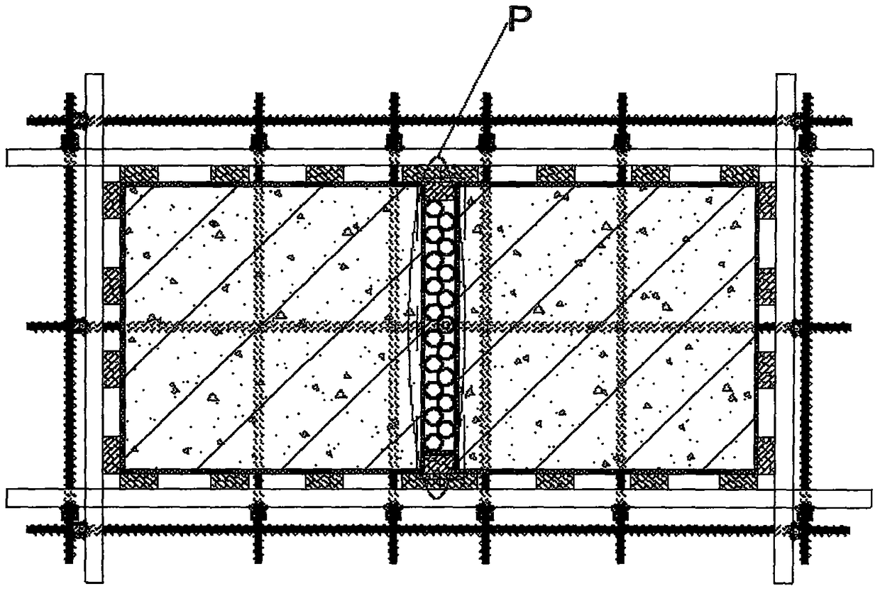

Image

  • An Easy-to-Remove Formwork Supporting Method of Deformation Seam
  • An Easy-to-Remove Formwork Supporting Method of Deformation Seam
  • An Easy-to-Remove Formwork Supporting Method of Deformation Seam

Examples


specific Embodiment 1

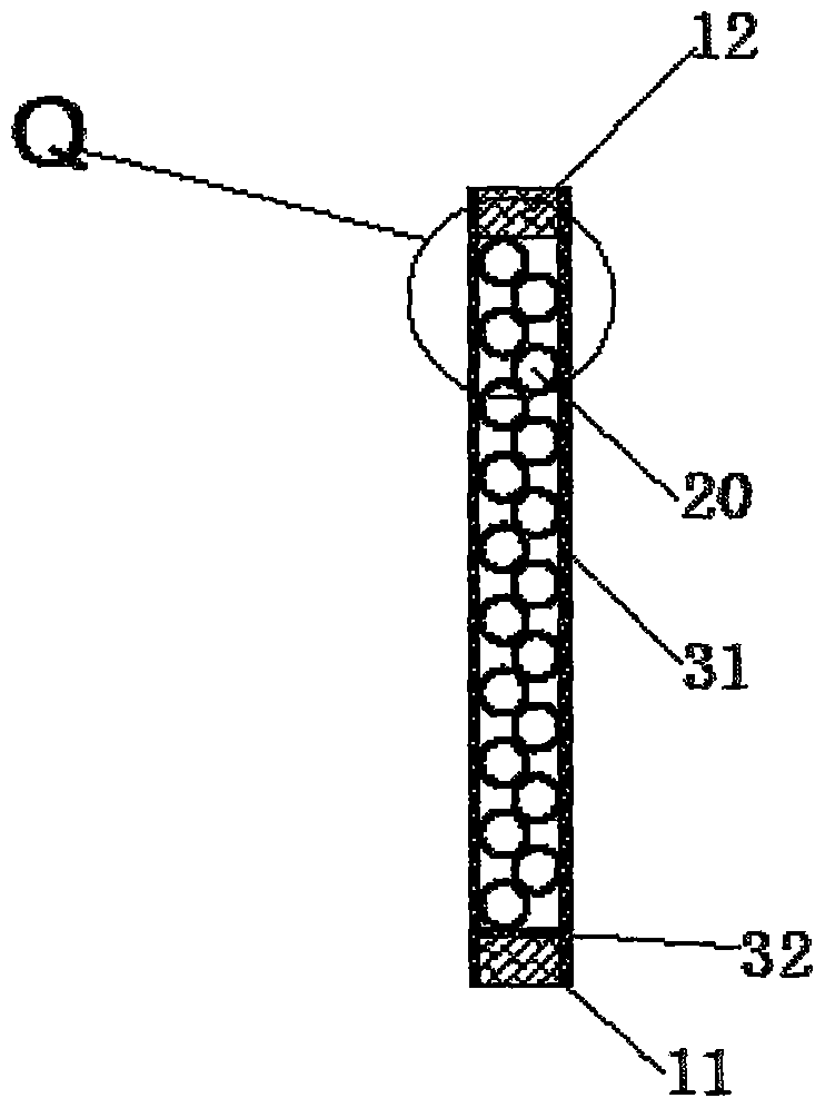
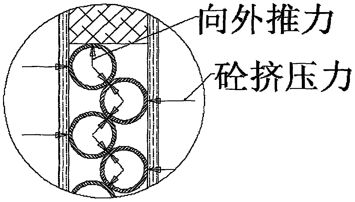
[0036] Such as Figure 1~3 As shown, an easy-to-remove deformation joint formwork method includes the following steps:

[0037] (1), install the first wood plywood 31 with thickness of 10mm respectively on both sides of the deformation joint;

[0038] (2), laying the first wooden side 11 with a thickness of 50mm at the bottom of the deformation joint;

[0039] (3), put into the scaffolding pipe 20 in the deformation seam successively, until the scaffolding pipe 20 is apart from the upper surface 80mm, the outer diameter of the scaffolding pipe 20 is 60% of the deformation seam gap,

[0040] (4), then a second wooden side 12 is set above the scaffolding pipe 20, and the height of the second wooden side is 80mm.

[0041] Further, when under pressure, there is an oblique thrust between adjacent scaffolding tubes 20, and the angle between the oblique thrust is 40°.

[0042] Further, in step (2), a second wood veneer 32 is provided on the upper surface of the first wooden cube 1...

specific Embodiment 2

[0043] An easy-to-remove deformation joint formwork method, comprising the following steps:

[0044] (1), install thickness respectively on the both sides of deformation joint and be the first wood plywood 31 of 12mm;

[0045] (2), laying the first wooden side 11 with a thickness of 50mm at the bottom of the deformation joint;

[0046] (3), put into the scaffolding pipe 20 in the deformation seam successively, until the scaffolding pipe 20 is apart from the upper surface 100mm, the outer diameter of the scaffolding pipe 20 is 55% of the deformation seam gap,

[0047] (4), then set the second wooden side 12 above the scaffold pipe 20, the height of the second wooden side 12 is 100mm.

[0048] Further, when under pressure, there is an oblique thrust between adjacent scaffolding tubes 20, and the angle between the oblique thrust is 50°.

[0049] Further, in step (2), a second wood veneer 32 is also provided on the upper surface of the first wooden cube 11 . The height of the s...

specific Embodiment 3

[0050] An easy-to-remove deformation joint formwork method, comprising the following steps:

[0051] (1), the thickness is respectively installed on both sides of the deformation joint and is the first wood plywood 31 of 11mm;

[0052] (2), laying the first wooden side 11 with a thickness of 50mm at the bottom of the deformation joint;

[0053] (3), put into the scaffolding pipe 20 in the deformation seam successively, until the scaffolding pipe 20 is apart from the upper surface 50mm, the outer diameter of the scaffolding pipe 20 is 65% of the deformation seam gap,

[0054] (4), then the second wooden side 12 is set on the top of the scaffold pipe 20, and the height of the second wooden side 12 is 50mm.

[0055] Further, when under pressure, there is an oblique thrust between adjacent scaffolding tubes 20, and the included angle of the oblique thrust is 45°.

[0056] Further, in step (2), a second wood veneer 32 is also provided on the upper surface of the first wooden cube...


PUM


Abstract

The invention relates to an easy-to-dismantle deformation joint form erecting method which comprises the following steps: (1) mounting first wood glue plates which are 1 to 12mm thick on the two sides of a deformation joint respectively; (2) laying a first batten which is 50mm thick at the bottom of the deformation joint; (3) sequentially placing scaffold tubes in the deformation joint until the distance between the scaffold tubes and the upper surface is smaller than 100mm; (4) arranging a second batten above the scaffold tubes. The easy-to-dismantle deformation joint form erecting method has the beneficial effects that (1) easiness for dismantling is achieved; (2) such a combination is stiff enough, and the structural dimensions on the two sides of the deformation joints can be ensured; (3) the adopted materials are common for construction, and can be recycled; (4) the two sides of the deformation joints are simultaneously constructed, so that the construction speed is increased.

Description

technical field [0001] The invention belongs to the technical field of construction engineering, and in particular relates to an easy-to-remove deformation joint formwork support method. Background technique [0002] Deformation joints can be divided into three types: expansion joints, settlement joints, and seismic joints. [0003] Expansion joints: Building components will expand and shrink due to changes in temperature and humidity. For this reason, vertical gaps are usually set at appropriate parts of the building, and the wall, floor, roof and other components of the house are disconnected from the foundation, and the building is separated into several independent parts. For the seams set up to overcome the excessive temperature difference, the foundation may not be disconnected, and the structure is disconnected from the top surface of the foundation to the roof. [0004] Seismic joints: The joints set up to make the building more regular and beneficial to the struct...

Claims


Application Information

Patent Timeline
Patent Type & Authority Patents(China)
IPC IPC(8): E04G15/00
Inventor 边聪伟王俊如
Owner NORTH CHINA METALLURGICAL CONSTR ENG CONSTR
Learn More