Reset mechanism of mold push plate

A technology of reset mechanism and push plate, which is applied in the field of push plate reset mechanism, can solve problems such as error, contact position error of travel switch, inaccurate contact position of travel switch, etc., and achieve zero drift, good tooth surface meshing, tooth surface The effect of little wear

Inactive Publication Date: 2012-01-25
SHUNDE POLYTECHNIC
View PDF3 Cites 12 Cited by
  • Summary
  • Abstract
  • Description
  • Claims
  • Application Information

AI Technical Summary

Problems solved by technology

However, there is also a problem with using the travel switch to determine the reset of the push plate, that is, the contact position of the travel switch determined manually is actually not accurate. The main manifestations are: 1. The initial positioning depends on manual operation, and there are errors in the determination of the contact position of the travel switch , that is, after the contact between the push plate and the movable platen, the "tightness" of the travel switch contact is not guaranteed, so there must be an error, which may cause a small gap between the push plate and the movable platen or theoretical interference
2. The travel switch contact tightening screw may become loose during long-term operation, thus indicating the wrong position of the push plate; 3. The stability of the travel switch is yet to be determined
In the actual injection molding process, the travel switch must work continuously and guaranteed. In the current situation, although it can be repeated many times in the experimental system, the long-term stability of the method of determining the zero position of the push plate has not been verified.

Method used


Image

  • Reset mechanism of mold push plate
  • Reset mechanism of mold push plate
  • Reset mechanism of mold push plate

Examples


Embodiment Construction

[0024] The present invention will be further described below in conjunction with the accompanying drawings and examples. It should be understood that the specific embodiments described here are only used to explain the present invention, and are not intended to limit the present invention.

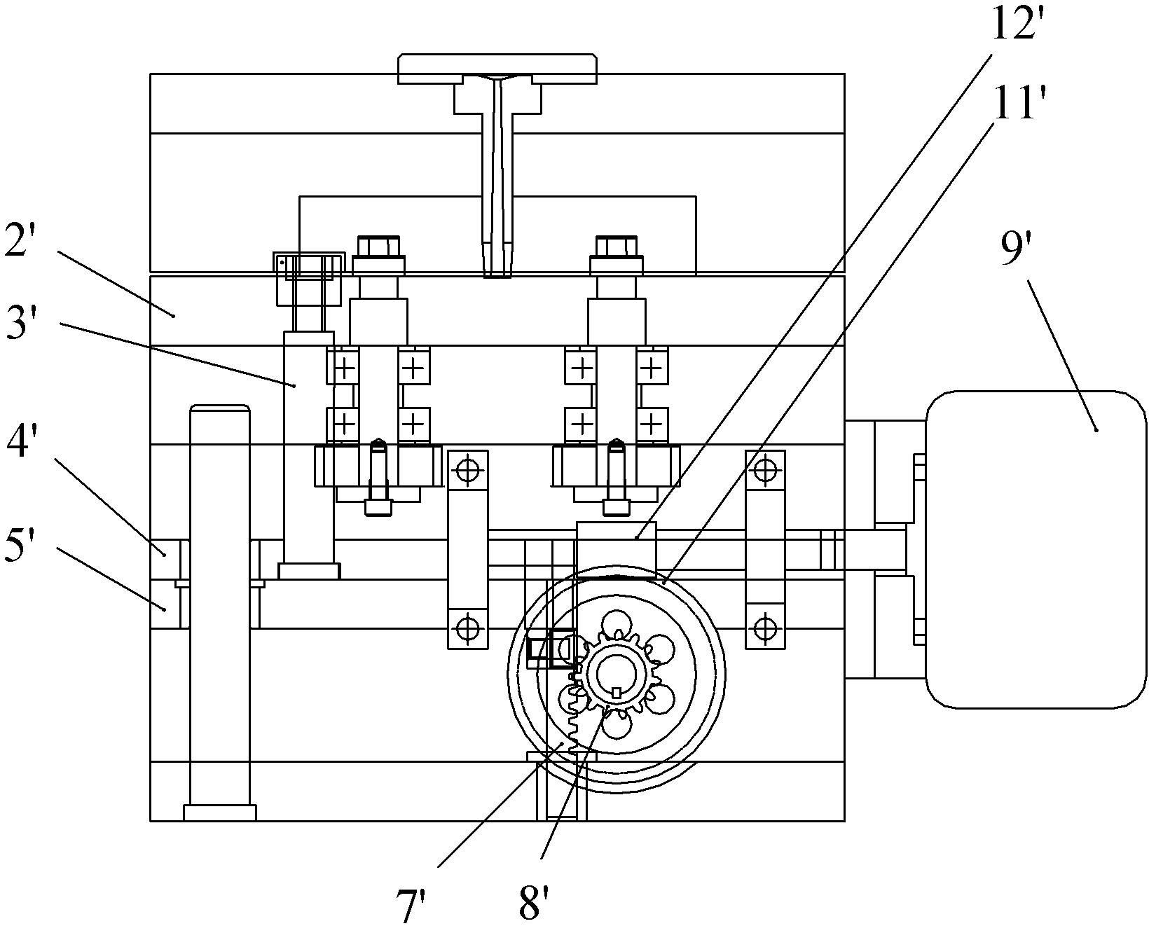
[0025] The mold push plate reset mechanism of the present invention comprises a fixed platen, a movable platen, a push plate, a threaded core, a rotating core-pulling mechanism, and a push plate ejection mechanism. The push plate ejection mechanism includes a servo motor and a sprocket drive pair, Screw nut drive pair. Such as figure 2 As shown, in the mold cavity of the injection mold is an injection molded part 2 with an internal thread structure, the movable template is below the push plate 11, the upper surface of the push plate 11 is close to the bottom surface of the injection molded part, and the fixed template is on the bottom of the injection molded part 2. The upper position is...


PUM


Abstract

The invention provides a reset mechanism of a mold push plate, and the reset mechanism comprises a fixed mold plate, a movable mold plate, a push plate, a threaded mold core, a rotating loose core connected with the threaded mold core and a push plate ejection mechanism connected with the push plate, as well as a PLC (programmable logic controller) synchronous control system for driving the rotating loose core mechanism and the push plate ejection mechanism, wherein the push plate ejection mechanism comprises a servo motor and a transmission pair for transforming the rotational motion of the servo motor to the ejection and withdrawal linear motion of the push plate, the PLC synchronous control system comprises a push plate ejection impulse stroke and a push plate reset impulse stroke, the servo motor of the push plate ejection mechanism is connected with a ratchet mechanism, the ratchet mechanism is connected with the transmission pair, and the push plate reset impulse stroke is larger than the push plate ejection impulse stroke. By additionally arranging the ratchet mechanism in a servo system, the zero drift problem of the servo system is solved in a simple and effective way, and the reset mechanism of the mold push plate has the advantages of reasonable structure, effective control and accurate reset.

Description

technical field [0001] The invention relates to a mold core-pulling mechanism, in particular to a push plate reset mechanism for servo synchronous automatic thread removal on an injection mold. Background technique [0002] In the injection mold, if there are threads in the plastic part, the thread core cannot be pulled out directly for forced release, otherwise the internal thread structure of the plastic part will be easily damaged. For this reason, the inventor has designed an internal thread automatic demoulding servo The synchronous mechanism connects the threaded core and the push plate with the rotating mechanism and the lifting mechanism respectively. The strokes of the two mechanisms are controlled by the control system, so that the axial speed of the rotating mechanism to unscrew the thread is consistent with the speed of the lifting mechanism pushing out the push plate. The threaded core is connected to the rotating shaft, and is connected to the rotating mechanis...

Claims


Application Information

Patent Timeline
Patent Type & Authority Applications(China)
IPC IPC(8): B29C45/40
Inventor 畅国帏乡碧云
Owner SHUNDE POLYTECHNIC
Why Eureka
Try Eureka