Method and circuit for carrying out compensation on additional phase drift of Y-shaped waveguide

A technology of phase drift and waveguide, which is applied in the direction of measuring electrical variables, measuring current/voltage, measuring devices, etc., can solve the problems of cumbersome implementation process, difficult and cumbersome algorithm implementation, and achieve strong anti-interference ability, easy engineering implementation, Achieve the effect of simple process

Active Publication Date: 2014-04-23
XIAN SINO HUAXIN MEASUREMENT & CONTROL
View PDF4 Cites 0 Cited by
  • Summary
  • Abstract
  • Description
  • Claims
  • Application Information

AI Technical Summary

Problems solved by technology

[0008] Among the above three compensation schemes, the digital temperature sensor used in scheme 1 is difficult to take into account the accuracy and response speed; on the other hand, the temperature drift data for each gyroscope can only be written into the FPGA program of the fiber optic gyroscope, and the implementation process is very cumbersome. Difficult to engineer
[0009] When Scheme 2 adopts the four-state square wave modulation scheme of the second feedback loop, when the spectral shape of the light source is asymmetrical, a greater error will be introduced; the algorithm is difficult to implement; it is too dependent on the performance of the system itself, especially when it is affected by external interference noise When affected, it is easy to cause system crashes and errors
[0010] The negative refractive index temperature coefficient crystal introduced in Scheme 3 destroys the packaging structure of the Y-shaped waveguide, making it difficult to ensure the reciprocity of the optical path; small cutting and alignment errors in the processing process will cause greater errors in the optical path
[0011] Therefore, these current solutions are complex and cumbersome in technology, and it is urgent to find a more ideal solution

Method used


Image

  • Method and circuit for carrying out compensation on additional phase drift of Y-shaped waveguide
  • Method and circuit for carrying out compensation on additional phase drift of Y-shaped waveguide
  • Method and circuit for carrying out compensation on additional phase drift of Y-shaped waveguide

Examples


Embodiment Construction

[0036] The present invention proposes a method and a circuit for compensating the additional phase drift of a Y-shaped waveguide based on a thermistor. The method includes the following steps:

[0037] 1) Obtain the analog signal to be applied to the Y-shaped waveguide;

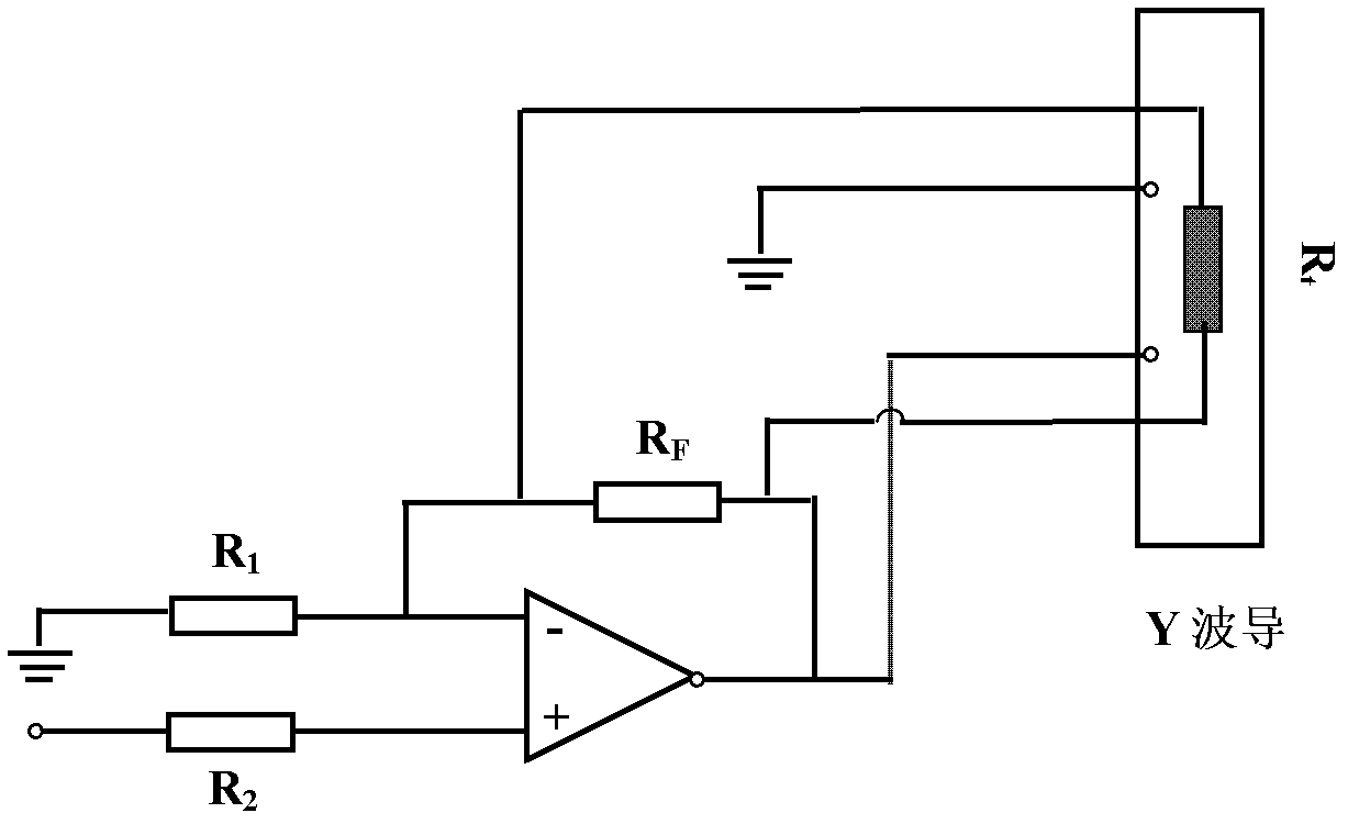
[0038] 2) The analog signal obtained in step 1) is amplified through an operational amplifier circuit, and the operational amplifier circuit includes a thermistor, a first resistor, a second resistor, and a feedback resistor R F and integrated operational amplifiers. The input voltage is connected to the integrated operational amplifier through the first resistor or the second resistor. The first resistor and the second resistor are respectively connected to the inverting and non-inverting input terminals of the integrated operational amplifier. The output voltage is passed through the feedback resistor R F Lead back to the inverting input of the integrated operational amplifier. The magnification of the ...


PUM


Abstract

The invention relates to a method and a circuit suitable to carry out compensation on an additional phase drift of a Y-shaped waveguide based on a thermosensitive resistor in an optical fiber gyroscope, an optical fiber current sensor and other relevant optical fiber sensors. The method comprises the following steps: (1), obtaining an analog signal to be applied onto the Y-shaped waveguide; (2), carrying out amplification processing on the analog signal obtained in the step (1) through an operational amplifying circuit, wherein an amplification factor is determined by the operational amplifying circuit; (3), carrying out reverse compensation on the amplification factor in the step (2) to obtain a compensated modulating voltage to be applied onto the Y-shaped waveguide; and (4), applying the compensated modulating voltage onto the Y-shaped waveguide. The invention provides the method and the circuit for carrying out the compensation on the additional phase drift of the Y-shaped waveguide, which have a simple process, is easy for engineering realization, and have low cost and no damage to a favorable encapsulating structure of the Y-shaped waveguide.

Description

technical field [0001] The invention belongs to the field of optical fiber sensing, and relates to a method and a circuit for compensating the additional phase drift of a Y-shaped waveguide, in particular to a Y-type sensor based on a thermistor in an optical fiber gyroscope, an optical fiber current sensor and other related optical fiber sensors. A method and circuit for compensating waveguide additional phase drift. Background technique [0002] The Y-waveguide used in the interferometric fiber optic gyroscope is an important optical device with multiple functions packaged using integrated optics technology. The Y-shaped waveguide mainly provides three major functions: beam splitting, polarization, and phase modulation. Among them, the phase modulation part is the most important, and it is also most seriously affected by temperature interference. The Y-shaped waveguide phase modulation part is made of LiNbO 3 Crystal packaged. Due to the linear electro-optic effect, in...

Claims


Application Information

Patent Timeline
Patent Type & Authority Patents(China)
IPC IPC(8): G01D3/032G01C25/00G01R19/32
Inventor 徐金涛王英利刘尚波王辉
Owner XIAN SINO HUAXIN MEASUREMENT & CONTROL
Why Eureka
Try Eureka