LED (Light Emitting Diode) bulb
A technology of LED light bulbs and LED light sources, applied in the field of lighting, can solve problems such as unsatisfactory lighting effects and poor heat dissipation capabilities of bulbs, and achieve the effects of increasing overall heat dissipation capabilities, increasing heat dissipation capabilities, and good irradiation effects
- Summary
- Abstract
- Description
- Claims
- Application Information
AI Technical Summary
Problems solved by technology
Method used
Image

Examples
Embodiment 1
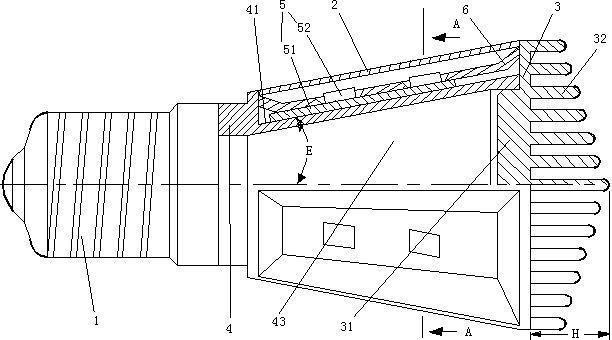
[0034] Embodiment one, see figure 1 , an LED light bulb, including a lamp base 1, six light-transmitting covers 2, a radiator 3 and a heat transfer body 4.
[0035] The lamp cap 1 is a screw lamp cap.
[0036] The heat transfer body 4 is a tubular structure with an inner hole 43 . The heat transfer body 4 is made of aluminum alloy. One end of the heat transfer body 4 is fixedly connected to the lamp cap 1 , and the other end of the heat transfer body 4 is fixedly connected to the radiator 3 .
[0037] The heat transfer body 4 is provided with six installation planes 41 . The installation plane 41 is an inclined plane inclined toward the lamp cap 1 . The inclination angle E of the installation plane is 25°.
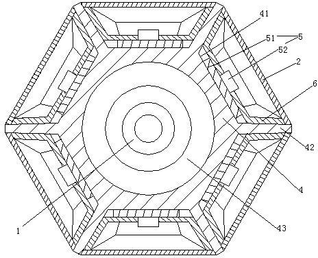
[0038] One LED light source assembly 5 is installed on each installation plane 41 . A reflector 6 is installed on the LED light source assembly 5 , and the light-transmitting covers 2 are covered on the reflector 6 in one-to-one correspondence. The LED light source ...
Embodiment 2
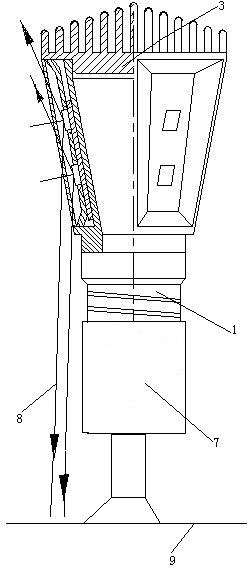
[0045] Embodiment two, see Figure 4 , The difference from Embodiment 1 is that the lamp cap 1 is a bayonet lamp cap. The heat transfer body 4 is a plate structure. The mounting plane 41 is only provided on one side of the heat transfer body 4 . No reflector is provided. The light-transmitting cover 2 is a truncated cone with a large top and a small bottom. The lower end of the transparent cover 2 is connected to the lamp cap 1 , and the upper end of the transparent cover 2 is connected to the radiator 3 . The heat transfer body 4 and the LED light source assembly 5 installed on the installation plane 41 are located inside the transparent cover 2 . The inclination angle E of the installation plane is 40°.
[0046] see Figure 5 , a cooling groove 44 is opened on the side of the heat transfer body 4 . The purpose of designing the heat dissipation groove 44 is to increase the heat dissipation area of the heat transfer body 4 .
[0047] see Image 6 The light bulb with...
Embodiment 3
[0048] Embodiment three, see Figure 7 , the difference from Embodiment 1 is that the LED lamp bead 52 is spherical. Two rows and three columns of LED lamp beads 52 are installed on each base 51 . The free ends of the heat dissipation protrusions 32 are located on the same spherical surface. No reflector is mounted on the mounting plane 41 .
[0049] see Figure 8 , the heat transfer body 4 is triangular truncated. Each side of the heat transfer body 4 constitutes a mounting plane 41 . The transparent cover 2 is in the shape of a truncated cone. The heat transfer body 4 is located in the same transparent cover 2 together with the three LED light source assemblies 5 respectively installed on the three installation planes.
PUM
 Abstract
Description
Claims
Application Information
 - R&D
- Intellectual Property
- Life Sciences
- Materials
- Tech Scout
- Unparalleled Data Quality
- Higher Quality Content
- 60% Fewer Hallucinations
Browse by: Latest US Patents, China's latest patents, Technical Efficacy Thesaurus, Application Domain, Technology Topic, Popular Technical Reports.
© 2025 PatSnap. All rights reserved.Legal|Privacy policy|Modern Slavery Act Transparency Statement|Sitemap|About US| Contact US: help@patsnap.com