
Analog loading test device of walking chassis speed changing box of combine harvester
A technology of loading test device and combine harvester, applied in the direction of machine gear/transmission mechanism testing, etc., can solve the problems of frequent land impact, large resistance, slow speed, etc., and achieve the effect of convenient manufacturing, advanced technology and good simulation effect.
- Summary
- Abstract
- Description
- Claims
- Application Information
AI Technical Summary
Problems solved by technology
Method used
Image

Examples
Embodiment Construction
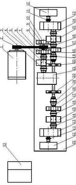
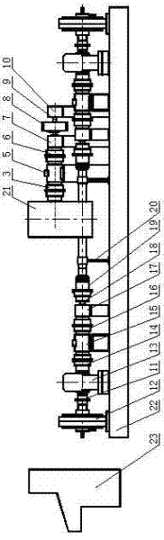
[0014] For device layout and transmission, please refer to figure 1 , figure 2 . Except for the speed-regulating drive motor 1 and the central control cabinet 23, all other working parts and transmission parts are fixed on the installation base 22 through the support. The drive pulley B8 is connected to the drive shaft 9, and the central control cabinet is the display controller of the test device, which is connected to the speed-regulating drive motor 1, magnetic powder brake 12 and various sensors through signal lines to provide control signals and display the collected data. During the test, first turn on the drive motor controller in the central control cabinet to make the speed-regulating drive motor rotate and output power. The torque speed sensor 5 and the shaft coupling A3 are transmitted to the gearbox 21 to be tested, wherein the sensor can measure the speed and torque of the driving power to help determine whether the test requirements are met. If the requirement...
PUM
 Abstract
Description
Claims
Application Information