
Method for detecting position of hub motor of PET-CT (Positron Emission Tomography-Computed Tomography) machine on basis of magnetic ring and Hall sensor

A technology of PET-CT and Hall sensor, which is applied in the field of motor position detection, can solve the problems of inaccurate motor position, low sensitivity, and large influence of external interference, etc., to weaken the magnetic field strength is too large or too small, and the response speed is fast , the effect of high control precision

Inactive Publication Date: 2012-01-25
DONGHUA UNIV
View PDF4 Cites 4 Cited by
  • Summary
  • Abstract
  • Description
  • Claims
  • Application Information

AI Technical Summary

Problems solved by technology

At present, encoder sensors, grating sensors, magnetic grid sensors, etc. are widely used in position detection. However, due to high price and cost, great influence of external interference, and high requirements for manufacturing and installation processes, at the same time, during the operation of the motor, Due to the inaccurate position and low sensitivity of the motor caused by the excessive or small magnetic field strength and magnetic asymmetry in the manufacture and operation of the motor, it has brought great challenges to the precise position detection and speed control of the motor.

Method used

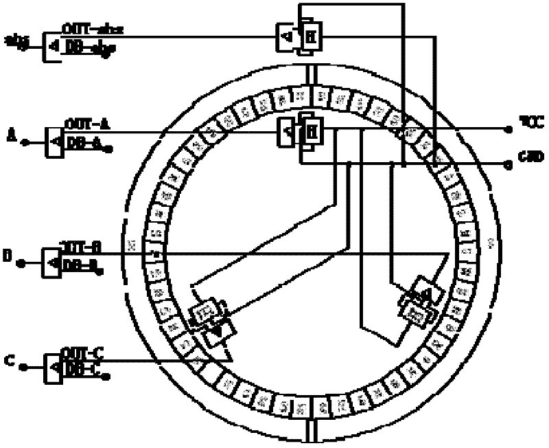
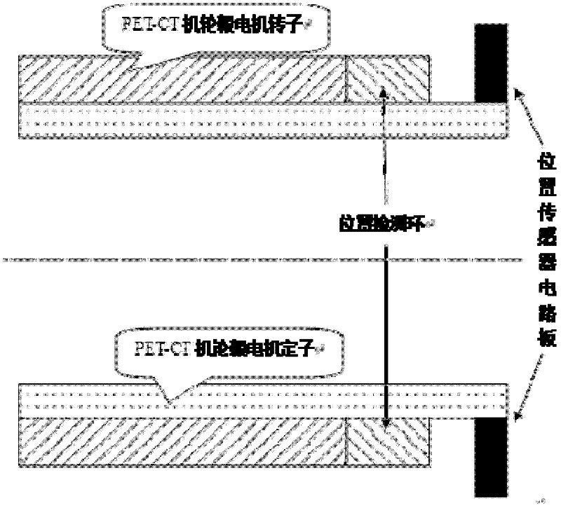

Image

  • Method for detecting position of hub motor of PET-CT (Positron Emission Tomography-Computed Tomography) machine on basis of magnetic ring and Hall sensor
  • Method for detecting position of hub motor of PET-CT (Positron Emission Tomography-Computed Tomography) machine on basis of magnetic ring and Hall sensor
  • Method for detecting position of hub motor of PET-CT (Positron Emission Tomography-Computed Tomography) machine on basis of magnetic ring and Hall sensor

Examples


Embodiment Construction

[0015] Below in conjunction with specific embodiment, further illustrate the present invention. It should be understood that these examples are only used to illustrate the present invention and are not intended to limit the scope of the present invention. In addition, it should be understood that after reading the teachings of the present invention, those skilled in the art can make various changes or modifications to the present invention, and these equivalent forms also fall within the scope defined by the appended claims of the present application.

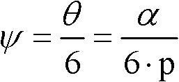
[0016] Such as Figure 1-2 As shown, the present invention relates to a high-precision position detection method of a hub motor of a PET-CT machine based on a magnetic ring and a Hall sensor, and the method is realized by a high-precision position detection device of a position detection ring and a Hall sensor. It includes a Hall sensor and a position detection ring, the Hall sensor is a linear Hall sensor, and the position de...


PUM


Abstract

The invention relates to a method for detecting the position of a hub motor of a PET-CT (Positron Emission Tomography-Computed Tomography) machine on the basis of a magnetic ring and a Hall sensor, which comprises the following steps of: in the operating process of the hub motor of the PET-CT machine, detecting a position detection ring driven by a rotor of the hub motor of the PET-CT machine by the linear Hall sensor, wherein the electromagnetic induction is generated between the linear Hall sensor and the position detection ring to generate a Hall electric potential; comparing the measured Hall electric potential with a standard value in a comparator, outputting a comparison result and judging whether the hub motor of the PET-CT machine operates to the accurate position or not by the comparison result; and when the hub motor of the PET-CT machine is started, after carrying out positioning and control of a rotating speed on an initial position of the motor by an absolute position sensor, ensuring the absolute position sensor to enter a detection state and controlling current phase conversion of the motor by a relative position sensor. Due to the adoption of the method for detecting the position of the hub motor of the PET-CT machine on the basis of the magnetic ring and the Hall sensor, the influence of position error, which is caused by the problems of magnetic asymmetry and strength of a magnetic field in the manufacturing and working process of magnetic steel of the motor of the PET-CT machine, is greatly weakened and the position accuracy of the motor is improved.

Description

technical field [0001] The invention relates to the technical field of motor position detection applications, in particular to a high-precision position detection method for a hub motor of a PET-CT machine based on a magnetic ring and a Hall sensor. Background technique [0002] With the rapid development of industrial production, the requirements for the position detection accuracy of motor work are getting higher and higher. At present, encoder sensors, grating sensors, magnetic grid sensors, etc. are widely used in position detection. However, due to the high price and cost, the influence of external interference, and the high requirements for manufacturing and installation processes, at the same time, during the operation of the motor, Due to the inaccurate position and low sensitivity of the motor caused by the excessive or small magnetic field strength and magnetic asymmetry in the manufacture and operation of the motor, it has brought great challenges to the precise p...

Claims


Application Information

Patent Timeline
IPC IPC(8): H02P6/16
Inventor 陈家新林毅杨文强李向坤
Owner DONGHUA UNIV
Learn More