Double-booster-pump system of precise machine room air conditioner

A computer room air conditioner and booster pump technology, applied in air conditioning systems, space heating and ventilation, household heating, etc., can solve problems such as increased energy consumption of air conditioners, poor cooling effect of air conditioners, and reduced operating efficiency of air conditioners

Active Publication Date: 2021-06-04
STATE GRID FUJIAN ELECTRIC POWER CO LTD +2
View PDF14 Cites 0 Cited by
  • Summary
  • Abstract
  • Description
  • Claims
  • Application Information

AI Technical Summary

Problems solved by technology

The working efficiency of the commonly used air-cooled air-conditioning system is difficult to meet the cooling requirements of the equipment, especially in the case of high outdoor ambient temperature, the cooling effect of the air-conditioning condenser

Method used


Image

  • Double-booster-pump system of precise machine room air conditioner
  • Double-booster-pump system of precise machine room air conditioner
  • Double-booster-pump system of precise machine room air conditioner

Examples


Embodiment 2

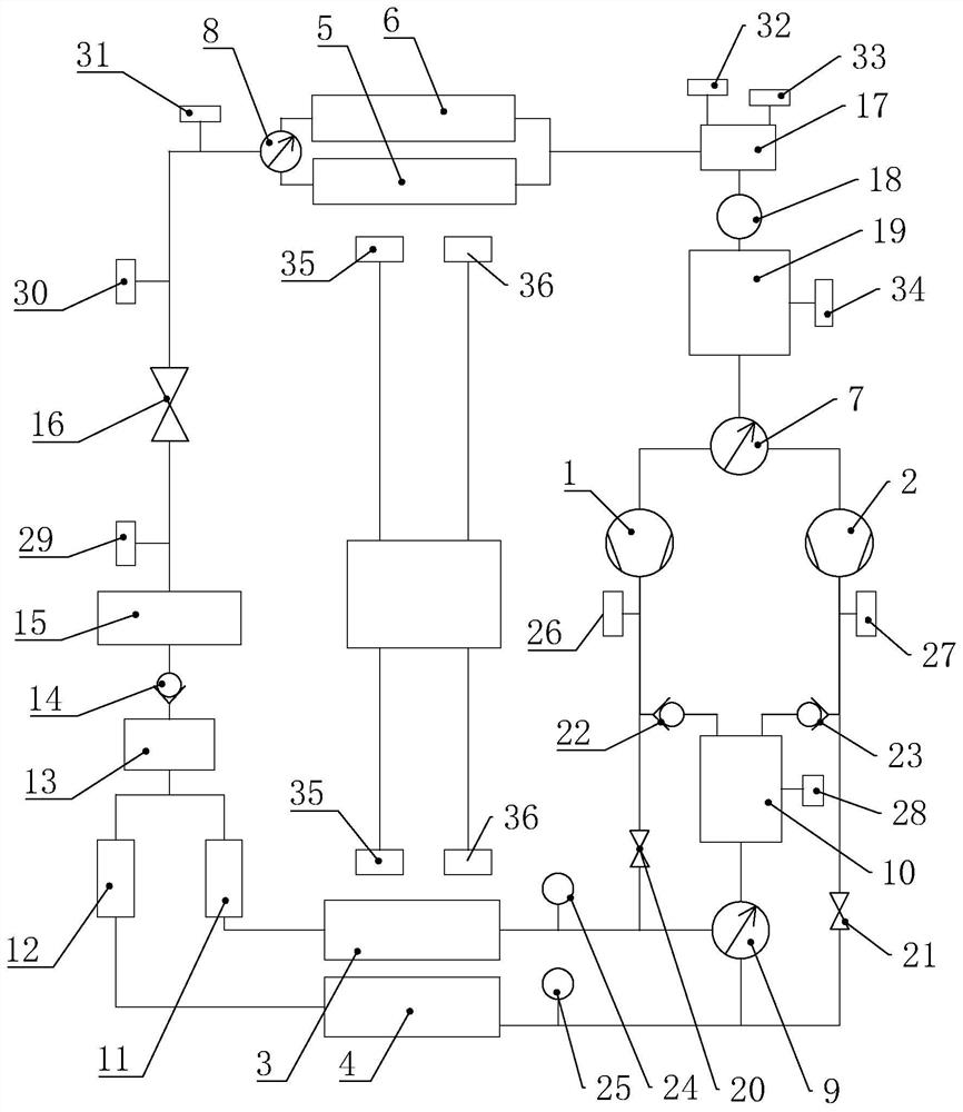
[0025] Embodiment 2. On the basis of Embodiment 1, the valve assembly further includes a first high-pressure regulating valve 20 disposed between the first booster pump 1 and the first condenser module 3, and a first high-pressure regulating valve 20 disposed between the second booster pump The second high-pressure regulating valve 21 between the pressure pump 2 and the second condenser module 4 and the first controllable check valve 22 and the second controllable check valve 22 respectively arranged on the two input ends of the pressure-stabilizing air storage tank 10 Valve 23; the sensor assembly includes a first pressure sensor 24 disposed between the first high pressure regulating valve 20 and the first condenser module 3, and a first pressure sensor 24 disposed between the first high pressure regulating valve 20 and the second condenser module 4 The second pressure sensor 25 between them, the third pressure sensor 26 and the fourth pressure sensor 27 respectively arranged ...

Embodiment 4

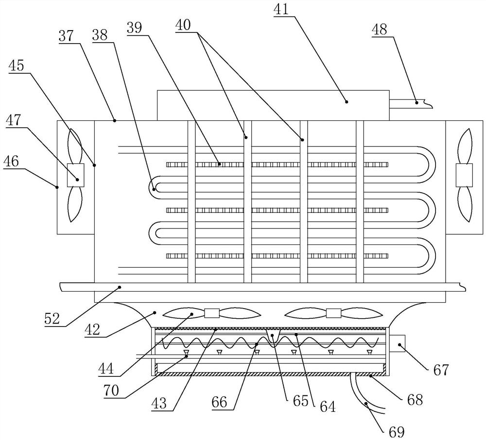
[0029] Embodiment 4: On the basis of Embodiment 3, a cleaning device and a spray device 70 are provided below the filter screen 43, and the cleaning device includes a guide rod 64 that is horizontally arranged below the filter screen 43, and the sliding connection on the guide rod 64 is useful. The brush head 65 used to clean the filter screen 43, the screw shaft 66 that drives the brush head 65 to move left and right, the screw shaft 66 is provided with a helical blade, and one end of the screw shaft 66 is connected with a driving motor 67, and the screw shaft 66 is provided below The water receiving tray 68 is connected with a sewage discharge pipe 69 at the bottom of the water receiving tray 68 . Water can be sprayed on the filter screen 43 through the spraying device 70, and the temperature of the air inlet 42 can be cooled while the filter screen 43 is cleaned, so that the temperature of the incoming air can be reduced by 1-2 degrees, which greatly improves the internal co...

Embodiment 6

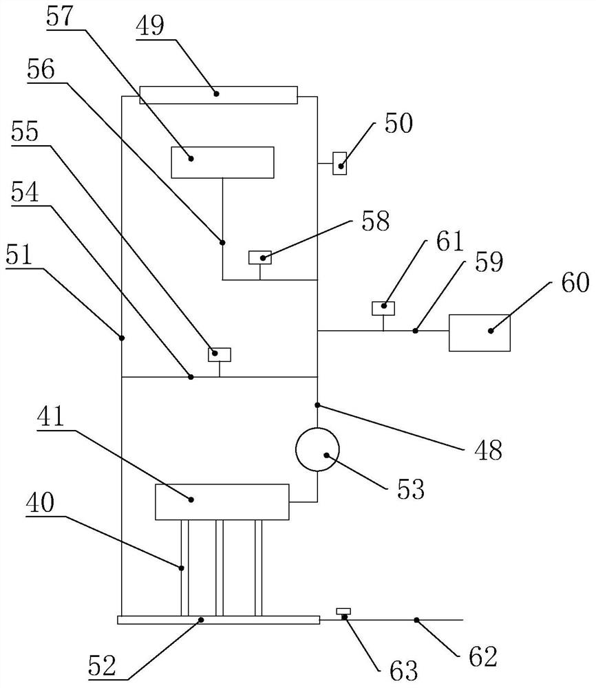
[0032] Embodiment 6: On the basis of Embodiment 5, a third water pipe 54 is provided between the first water pipe 48 and the second water pipe 51 , and a second electric control water valve 55 is provided on the third water pipe 54 . When the first electronically controlled water valve 50 is closed and the second electronically controlled water valve 55 is opened, a short water cycle can be constructed to improve heat exchange efficiency and enhance water cooling or water heating functions.


PUM


Abstract

The invention discloses a double-booster-pump system of a precise machine room air conditioner. The double-booster-pump system comprises an intelligent controller, a booster pump module, a sensor assembly, a valve assembly, a condenser module and an evaporator module. The booster pump module comprises a first booster pump and a second booster pump which are connected in parallel, the condenser module comprises a first condenser module and a second condenser module which are connected in parallel, and the valve assembly comprises a gas input distribution valve, a cold distribution valve and a gas output distribution valve. The first booster pump and the second booster pump are connected with the first condenser module and the second condenser module respectively, a pressure stabilizing gas storage tank is arranged between the first booster pump and the second booster pump and connected with the gas output distribution valve, and the gas output distribution valve is connected with the first condenser module and the second condenser module. The double-booster-pump system adopts double-evaporator, double-booster-pump and double-condenser design, thereby having high redundancy performance, load balance, high system operation safety and high natural cold source use efficiency.

Description

technical field [0001] The invention relates to the technical field of precision air conditioners, in particular to a dual booster pump system for precision machine room air conditioners. Background technique [0002] With the development of science and technology, the power consumption and heat generation of the machines in the data center are also increasing. The use of natural cold source technology has become a new trend in the cooling research of computer rooms in recent years. In winter and transitional seasons in most parts of my country and even the world, the outdoor temperature is lower than the indoor temperature of the computer room. Proper use of the cooling capacity of the outdoor air for cooling can replace the conventional vapor compression refrigeration to a certain extent, thereby saving power consumption. Therefore, on the premise of ensuring the safe operation of the equipment in the computer room, minimizing the energy consumption of the air conditioner ...

Claims


Application Information

Patent Timeline
IPC IPC(8): F24F1/0063F24F1/16F24F1/08
CPCF24F1/0063F24F1/16F24F1/08
Inventor 徐志光陈建洪范海威杨旭张明辉林钟馨陈洪刘必晶余斯航吕明亮周骏腾唐文昊林俊雄李真柯金发
Owner STATE GRID FUJIAN ELECTRIC POWER CO LTD
Why Eureka
Try Eureka