Digital phase locking amplifier and digital phase locking control method

A digital phase-locking and control method technology, applied in amplifiers, parametric amplifiers, amplifier types, etc., can solve problems such as large amount of calculation, limiting the speed of digital phase-locking detection and the frequency of the detected signal, and long time to complete the calculation. , to achieve the effect of high-precision measurement, fast calculation speed and short calculation time

CN102332878BActive Publication Date: 2013-12-18TIANJIN UNIV
1 Cites 0 Cited by

Patent Information

Authority / Receiving Office
CN · China
Patent Type
Patents(China)
Current Assignee / Owner
Publication Date
2013-12-18

Smart Images

  • Figure 1
    Figure 1
  • Figure 2
    Figure 2
  • Figure 3
    Figure 3
Patent Text Reader

Abstract

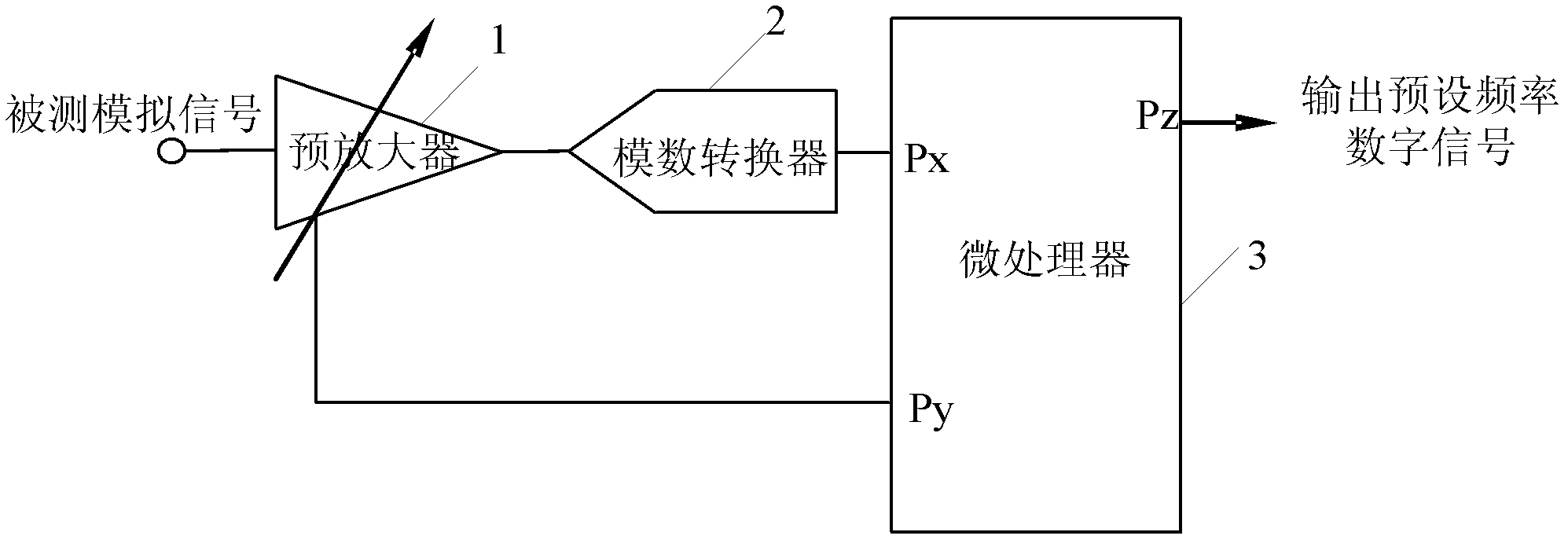
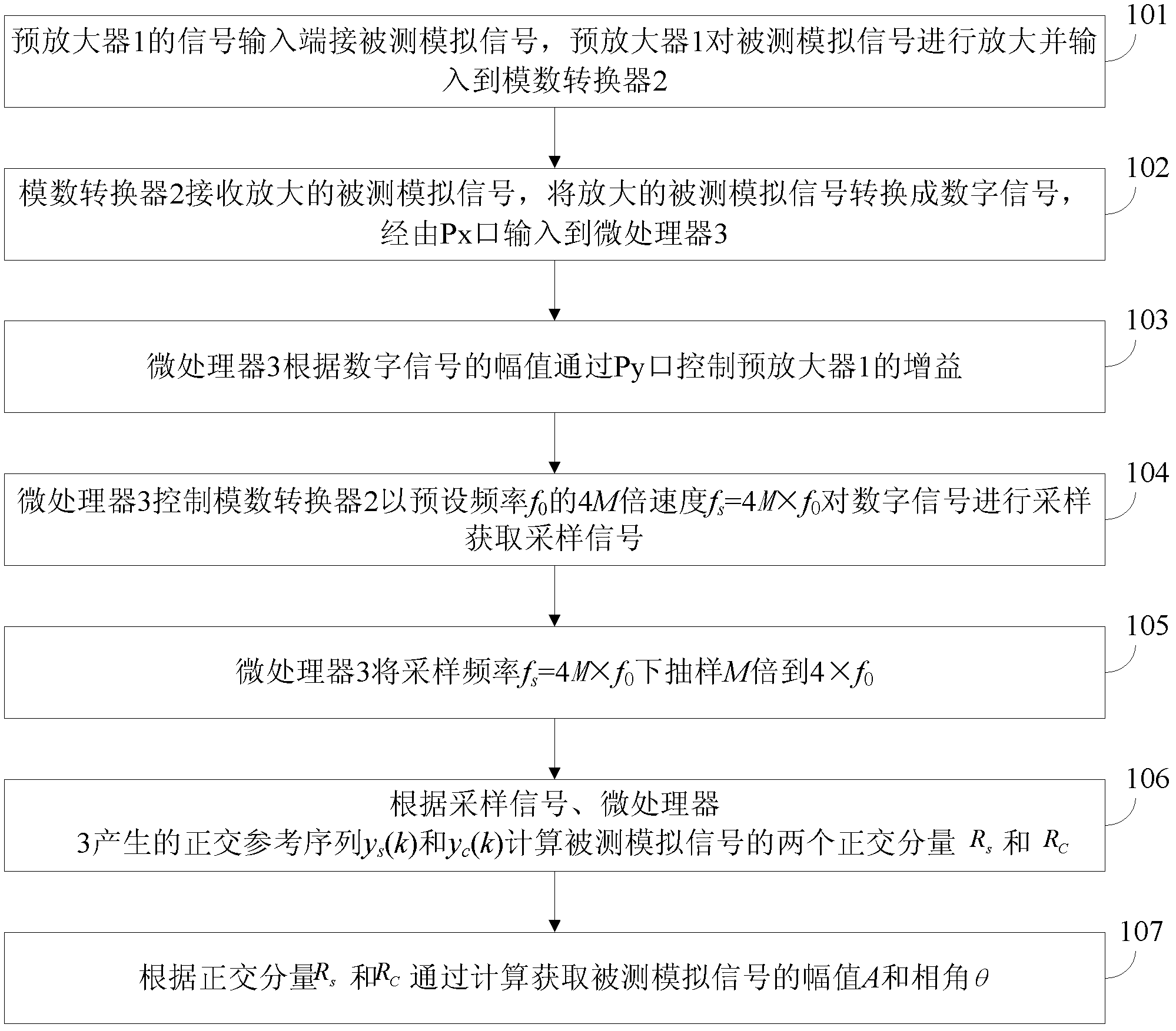
The invention discloses a digital phase locking amplifier and a digital phase locking control method. The digital phase locking amplifier comprises a pre-amplifier and a micro-processor. The pre-amplifier is used for amplifying a tested analogue signal, inputting the tested analogue signal into an analogue-digital converter, converting the amplified tested analogue signal into a digital signal, and inputting the digital signal into the micro-processor through a Px interface. The micro-processor is used for controlling the gain of the pre-amplifier through a Py interface according to the amplitude of the digital signal, processing the digital signal, detecting the digital signal with the pre-set frequency in the digital signal, and outputting the digital signal with the pre-set frequency through a Pz interface. The control method comprises the following steps: the micro-processor controls the analogue-digital converter to sample the tested analogue signal according to the speed which is 4M times of that of the pre-set frequency F0, represented in the equation of fs=4M*f0, so as to obtain a sampling signal; the micro-processor downwardly samples the sampling frequency fs=4M*f0 to 4*f0; two orthogonal components RS and RC of the tested analogue signal are calculated according to the sampling signal; and the amplitude A and the phase angle of the tested analogue signal can be obtained by calculation.
Need to check novelty before this filing date? Find Prior Art

Description

Technical field

[0001] The invention relates to a digital lock-in amplifier and a digital lock-in control method. Background technique

[0002] Single-frequency signal detection is the most common signal detection requirement, which is widely used in various measuring instruments and measurement and control systems. Nowadays, analog lock-in amplifiers (also called phase-lock detection circuits) are commonly used. This analog lock-in detection method has a series of shortcomings, such as complex circuits, high process requirements, and serious drift.

[0003] Compared with analog lock-in amplifiers, digital lock-in amplifiers can avoid all the drawbacks of analog circuits. The invention patent "A Digital Lock-in Amplifier" (publication number: CN101060311, publication date: October 24, 2007) proposed by Wang Zixin et al. uses a digital circuit to give a reference signal, which significantly improves the anti-interference performance of the circuit.

[0004] In the process of impleme...

Examples

Embodiment Construction

[0030] In order to make the objectives, technical solutions and advantages of the present invention clearer, the embodiments of the present invention will be described in further detail below in conjunction with the accompanying drawings.

[0031] Suppose the signal to be detected is x a (t)=Asin(2πf 0 t+θ), where A is the amplitude of the signal, f 0 Is the frequency of the signal, and θ is the initial phase angle. According to sampling frequency f s =M×f 0 Sampling, M≥2. The number of sampling cycles is N, the total number of sampling points Q=M×N, and the obtained sampling signal x(k) is:

[0032] x(k)=Asin(2πk / M+θ) k=0,1,2,......,Q-1 (1)

[0033] The reference sequence in digital phase lock is generated by the microprocessor 3 according to M, and the orthogonal reference sequence y S (k) and y C (k) are:

[0034] y S (k)=sin(2πk / M) k=0,1,2,......,Q-1 (2)

[0035] y C (k)=cos(2πk / M) k=0,1,2,......,Q-1 (3)

[0036] The collected signal x(k) and y S (k) and y C (k) Multiply to calcula...