Vehicle light

A vehicle and light source technology, applied in the direction of headlights, vehicle parts, vehicle lighting systems, etc., can solve the problems of low cost and achieve the effect of uniform brightness distribution

Active Publication Date: 2012-01-25
VOLKSWAGEN AG
View PDF4 Cites 6 Cited by
  • Summary
  • Abstract
  • Description
  • Claims
  • Application Information

AI Technical Summary

Problems solved by technology

Furthermore, the problem arises that the cost for manufacturing the lamp should be as small as possible

Method used


Image

  • Vehicle light
  • Vehicle light
  • Vehicle light

Examples


Embodiment Construction

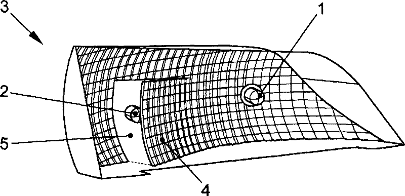
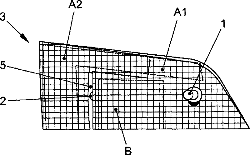
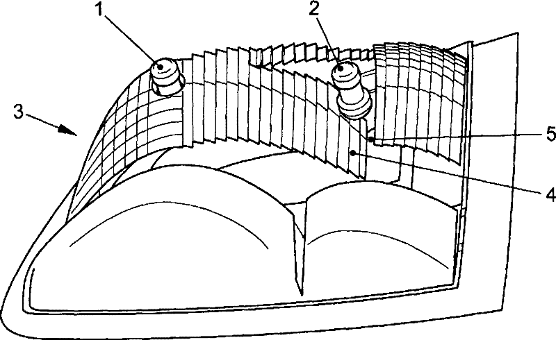
[0026] First, refer to Figures 1 to 3 Describe the basic structure of a lamp. The lights of the embodiment shown are tail lights. In the following, orientation specifications (such as horizontal, vertical and lateral) are directed to the installation of the lamp in the vehicle.

[0027] The lamp comprises a light source 1 . The light source 1 can here be a known light source 1 which is as point-shaped as possible. The light source 1 is arranged in front of the reflector 3 with respect to the light radiation direction of the lamp. For this purpose, the reflector 3 usually has a hole through which a support for the light source 1 can pass. However, such a location, ie at which the light radiation is generated, is located in front of the reflector with respect to the light radiation direction of the lamp. Obviously, it is possible here to form reflective regions laterally beside light source 1 that extend in front of the light source. However, on an axis running parallel t...


PUM


Abstract

The invention relates to a light for a vehicle having a contiguous reflector (3) having a plurality of reflector surface regions (A1, A2, B) and a first light source (1) that is arranged such that the light emission thereof is reflected by a first region (A1, B) of the reflector surface of the reflector (3). The light according to the invention is characterized in that the reflector (3) has an opening (5) and there is a second light source that is arranged behind a part (4) of the reflector (3) relative to the light emission direction (L) of the light and the light emission thereof hits a second region (A2) of the reflector surface of the reflector (3) through the opening (5) and is there reflected.

Description

technical field [0001] The invention relates to a lamp for vehicles with a continuous A reflector with a plurality of reflective surface regions and a first light source, the first light source being arranged in such a way that the light radiation of the first light source is reflected by the first regions of the reflective surface of the reflector. Background technique [0002] In the new design of vehicles, the problem arises that due to the desired aerodynamics and the desired design, the structural spatial relationship for the lighting unit, in particular for the lamps including taillights and headlights Dimensions are very compact (knapp). However, the signal effect of the lamp is determined by the perimeter dimensions and brightness of the emitting surface. Furthermore, headlights contribute to the design of the vehicle to a great extent. The shape (Gestaltung) of the lights should be multiplied to give the vehicle a unique, easily recognizable image (Erscheinungs...

Claims


Application Information

Patent Timeline
Patent Type & Authority Applications(China)
IPC IPC(8): F21S8/10F21S8/12
CPCF21S48/2212F21S48/23F21S41/334F21S41/336F21S43/26F21S43/30F21V7/06F21V21/26F21S41/335F21V7/04F21V7/09F21S41/32
Inventor M·胡佩尔H·基尔S·黑林S·福格勒
Owner VOLKSWAGEN AG
Why Eureka
Try Eureka