Electric vacuum cleaner

A vacuum cleaner and electric technology, applied in the field of control, can solve the problems of decreased dust attraction, decreased performance of dust removal, decreased performance of dust attraction, etc.

Inactive Publication Date: 2012-02-01
PANASONIC CORP
View PDF6 Cites 14 Cited by
  • Summary
  • Abstract
  • Description
  • Claims
  • Application Information

AI Technical Summary

Problems solved by technology

Therefore, there are cases where the performance of attracting dust, which is the original purpose of dust removal, is reduced, and even if the suction force is increased, the effect of attracting dust cannot be obtained.
As a result, there are problems such as loss of energy
[0005] That is to say, if the operation speed is slow, even if there is a lot of dust in the place to be cleaned, the suction force to attract dust decreases due to the reduction of suction force for dust removal, so that the original function of the electric vacuum cleaner cannot be satisfied.
In addition, there are problems such as the following: if the place to be cleaned is free of dust, even if the operation speed is increased to increase the suction force, it becomes a control that deviates from the purpose of the electric vacuum cleaner that attracts dust for cleaning.
For example, if the ground is a floor, even if the attraction force is increased, there may not be a large effect before and after raising the attraction force
On the other hand, for example, if the floor is carpeted, if the suction force is lowered, the dust removal performance will drop, so there may be cases where the dust cannot be sucked even if it is cleaned.
Therefore, there is a problem that dust cannot be completely removed by suction if only the suction is controlled in the above-mentioned ground state.

Method used


Image

  • Electric vacuum cleaner
  • Electric vacuum cleaner
  • Electric vacuum cleaner

Examples


Embodiment approach 1

[0036] use figure 1 The vacuum cleaner according to Embodiment 1 of the present invention will be described through FIG. 5 .

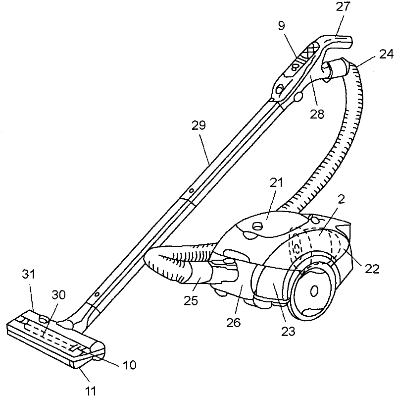
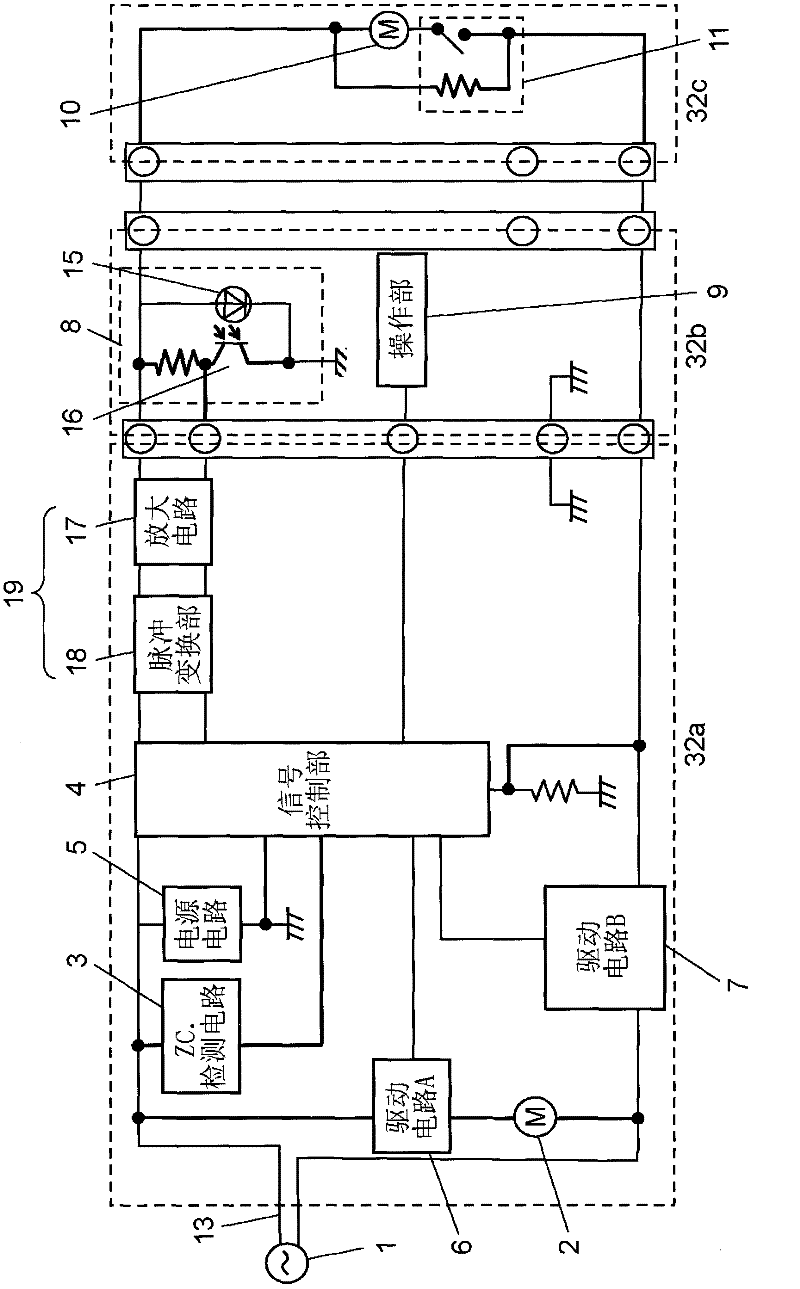
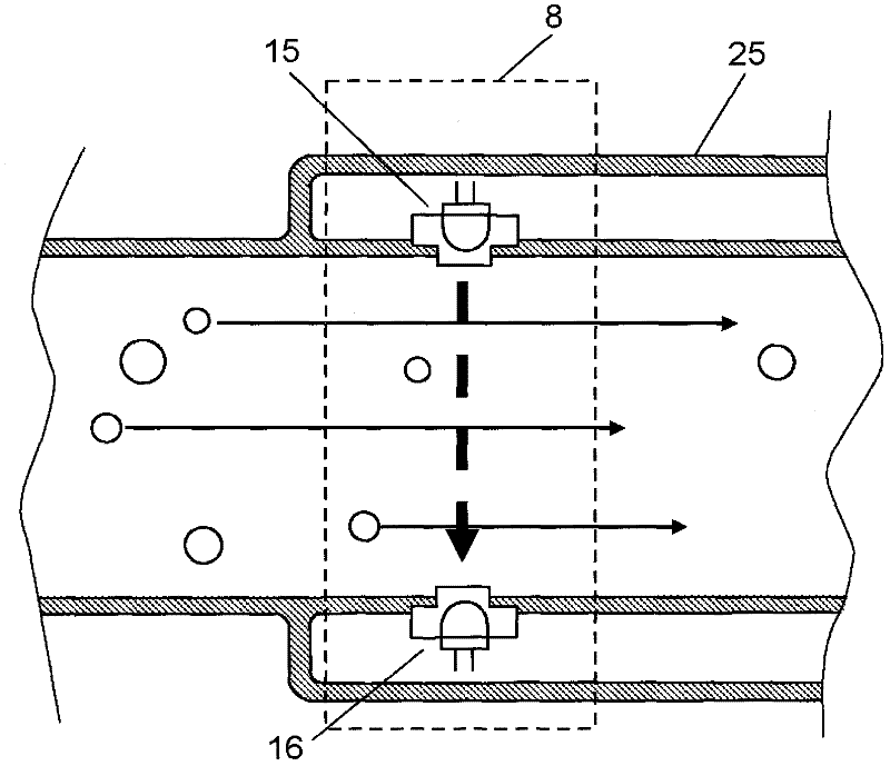
[0037] figure 1 It is an overall perspective view of the electric vacuum cleaner of this embodiment. figure 2 Is the circuit block diagram of the electric vacuum cleaner. image 3 It is a sectional view showing the structure of the dust sensor of this electric vacuum cleaner. Figure 4A It is a figure which shows the output waveform (in the case of a floor) of the dust sensor of this electric vacuum cleaner. Figure 4B It is a figure which shows the output waveform (in the case of a carpet) of this dust sensor. Figure 5A , Figure 5B It is a flowchart explaining the control of this electric vacuum cleaner.

[0038] figure 1 The vacuum cleaner main body 21 of the electric vacuum cleaner of this embodiment shown has the electric blower chamber 22 arrange|positioned in the rear part, and the electric blower 2 built in, and the dust collection cha...


PUM


Abstract

The invention provides an electric vacuum cleaner, which is provided with: a vacuum cleaning head provided with an electromotor performing rotation and drive of a rotary brush; a movement speed detection part detecting movement speed of the vacuum cleaning head; a circuit detecting part detecting ground state; an electric air blower making the vacuum cleaning head generate attraction force; a collection dust detection part detecting the attracted dust; a signal control part controlling the revolution of the electromotor and the electric air blower according to the movement speed detection part, the circuit detecting part, and the collection dust detection part. Therefore, the ground state can be mastered, making the revolution of the electromotor and the electric air blower collect dust optimally.

Description

technical field [0001] The present invention relates to an electric vacuum cleaner used for cleaning in general households, etc., and particularly relates to control related to user's operability and usability. Background technique [0002] Conventionally, the operation time and operation speed of the reciprocating motion when the user operates the electric vacuum cleaner are calculated from the number of reciprocating motions of the cleaning head per unit time, and the like. In addition, for example, Japanese Unexamined Patent Application Publication No. 3-82430 (Patent Document 1) proposes an electric vacuum cleaner that sucks dust and the like by changing the suction force based on the calculated result. [0003] However, in the environment where cleaning is actually performed, the cleaning methods of users vary greatly, and there are various operating methods and processing methods. Therefore, cleaning methods vary greatly depending on conditions such as the user's life...

Claims


Application Information

Patent Timeline
Patent Type & Authority Applications(China)
IPC IPC(8): A47L9/28
Inventor 上野圣一伊藤昭人曾根健次浅野功
Owner PANASONIC CORP
Why Eureka
Try Eureka