Power tool

A power tool and power output technology, applied in the field of power tools, can solve problems such as different adjustment directions and inconvenient operation

Active Publication Date: 2012-02-01
POSITEC POWER TOOLS (SUZHOU) CO LTD
View PDF15 Cites 9 Cited by
  • Summary
  • Abstract
  • Description
  • Claims
  • Application Information

AI Technical Summary

Problems solved by technology

[0009] However, although the adjustment of speed and the switching of functions are realized by a common button in the '839 patent, the adjustment direction of the button during speed adjustment and the adjustment direction of the button during function switching are different, which brings inconvenience to the operation.

Method used


Image

  • Power tool
  • Power tool
  • Power tool

Examples


Embodiment Construction

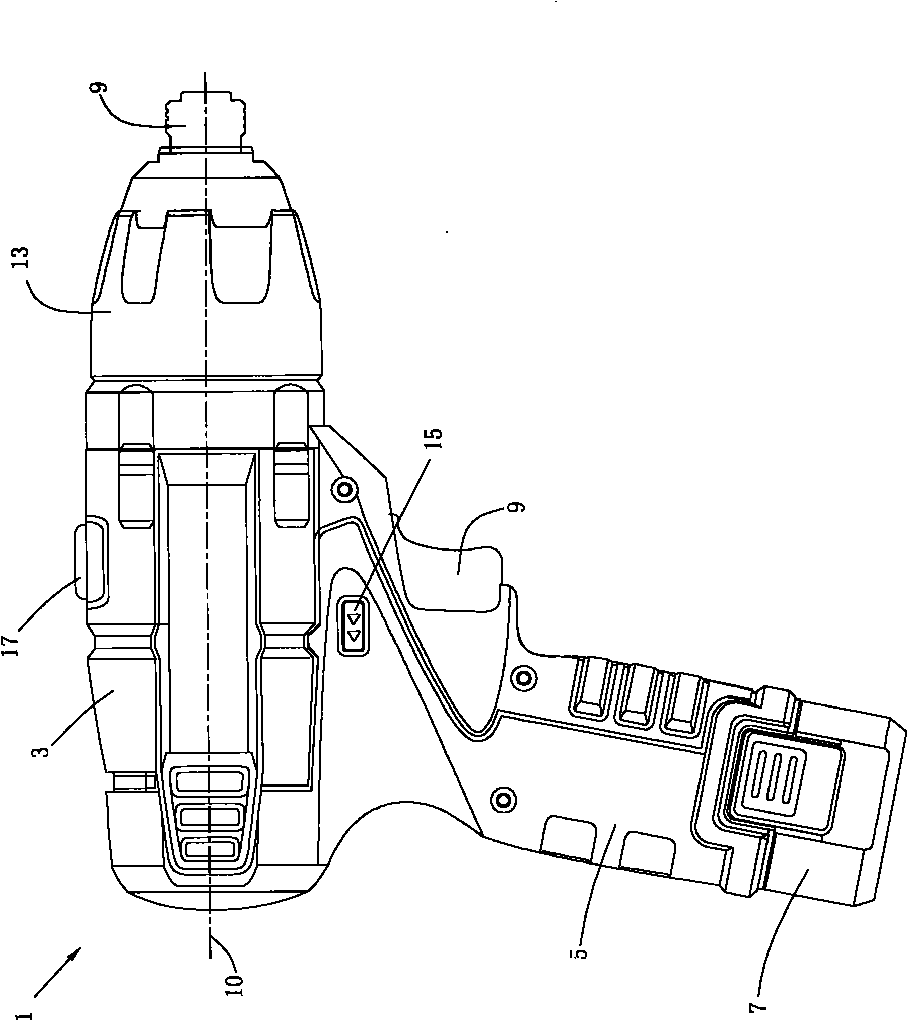
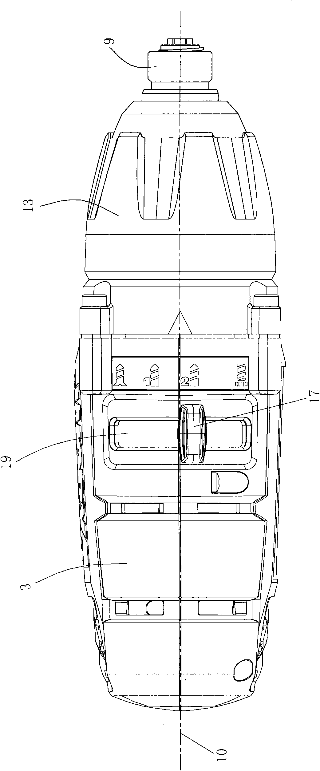
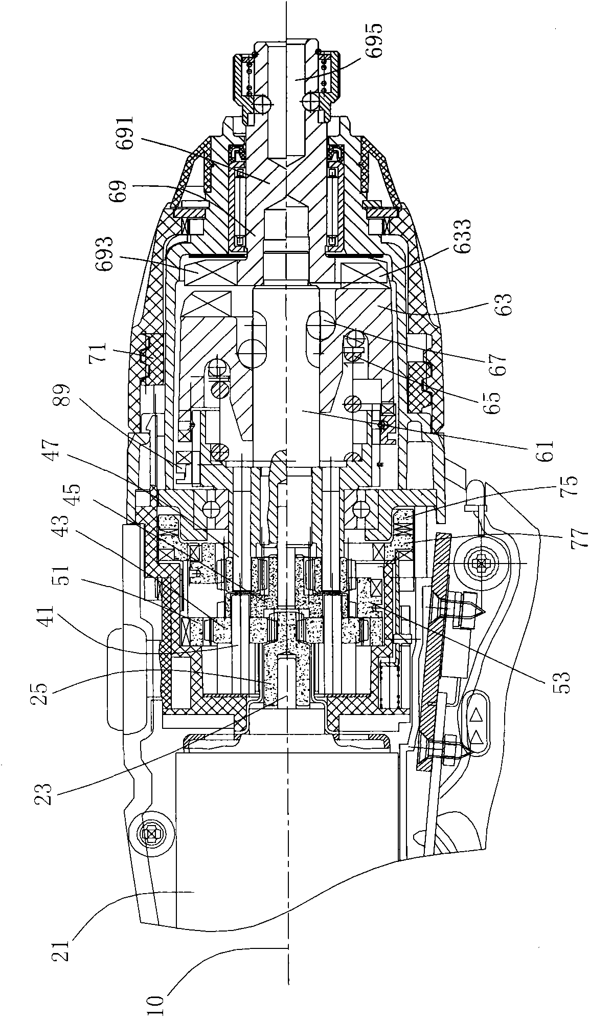
[0096] Figure 1 to Figure 17 What is shown is a specific embodiment of the power tool of the present invention, and the power tool is specifically a multifunctional drill 1 . The multi-function drill 1 has the functions of impact wrench, high-speed drill, low-speed drill, and screwdriver. The high-speed drill and low-speed drill can also be collectively referred to as the drilling function.

[0097] Such as figure 1 As shown, the multifunctional drill 1 is shaped like a pistol, and includes a substantially cylindrical housing 3 , a handle 5 arranged at an angle to the housing 3 , and a detachable battery pack 7 disposed at the bottom of the handle 5 . The housing 3 has a longitudinal axis 10 .

[0098] The front end of the housing 3 is provided with a collet 9 for clamping the working head, which is used to respectively clamp different working heads (not shown) when the multifunctional drill 1 realizes different functions, such as clamping when realizing the impact wrench f...


PUM


Abstract

The invention relates to a power tool. The power tool comprises a shell, a motor, a planetary gear deceleration system, a power output system, a switching window, and a function switching button; the motor is positioned in the shell and is provided with an output shaft which provides rotary output; the planetary gear deceleration system decelerates the rotary output of the output shaft and then performs rotary output; the power output system transfers the rotary output of the planetary gear deceleration system to a work head; the switching window is positioned on the shell; and at least one part of the function switching button is accommodated in the switching window, and the function switching button moves in the switching window to select an impact wrench function, a high-speed drilling function, a low-speed drilling function and a screwdriver function for the power tool. The function switching button can slide on the shell to realize speed regulation, and the impact wrench function can be switched, so that operation convenience is improved.

Description

technical field [0001] The invention relates to a power tool, especially a power tool that can switch between multiple functions. Background technique [0002] Existing gun drill power tools generally include electric drills, electric screwdrivers, impact drills, impact wrenches, and the like. [0003] Electric screwdrivers are used to tighten screws onto workpieces. It usually includes an overload clutch structure, which is composed of a clutch driving part and a driven part. The driving part is integrated with the reduction gear, while the driven part is rotatably fixed in the casing and can move axially relative to the casing. A working spring acts on the end face teeth of the driving part through the driven part, so that the driving part is fixed in the direction of rotation and the torque can be transmitted to make the screwdriver rotate. During operation, the torque of the motor is transmitted to the screwdriver through the planetary gear reduction mechanism to make ...

Claims


Application Information

Patent Timeline
Patent Type & Authority Applications(China)
IPC IPC(8): B25F3/00B25F5/00
Inventor 李成道纪明波
Owner POSITEC POWER TOOLS (SUZHOU) CO LTD
Why Eureka
Try Eureka