Diaphragm coupling with low additional bending moment

An additional bending moment and coupling technology, which is applied in the direction of couplings, elastic couplings, mechanical equipment, etc., can solve the problem that the diaphragm coupling has a large weight, a large additional bending moment, and cannot meet high-speed and high-power transmission. To achieve the effect of light weight, low additional bending moment and simple structure

Inactive Publication Date: 2012-02-01
无锡创明传动工程有限公司
View PDF4 Cites 3 Cited by
  • Summary
  • Abstract
  • Description
  • Claims
  • Application Information

AI Technical Summary

Problems solved by technology

The existing diaphragm coupling has a large weight and a large additional bending moment, which cannot meet the requirements of high-speed and high-power transmission fields

Method used


Image

  • Diaphragm coupling with low additional bending moment
  • Diaphragm coupling with low additional bending moment
  • Diaphragm coupling with low additional bending moment

Examples


Embodiment Construction

[0016] The present invention will be further described below in conjunction with specific drawings.

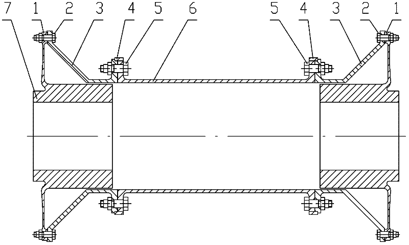
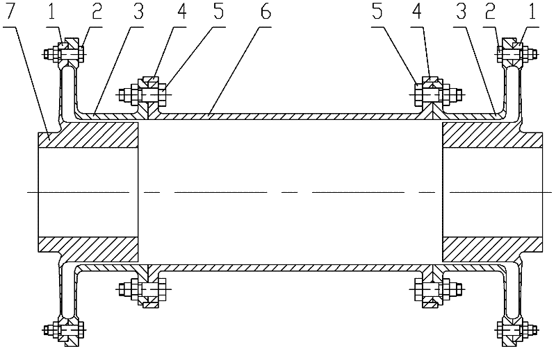
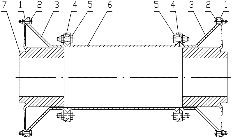
[0017] Such as Figure 1 ~ Figure 2 Shown: low additional bending moment diaphragm coupling includes diaphragm 1, first bolt assembly 2, adapter plate 3, positioning ring 4, second bolt assembly 5, intermediate spacer shaft 6, mounting plate 7, diaphragm method Lan 8 et al.

[0018] The present invention includes an intermediate shaft 6, a diaphragm 1 symmetrically installed at both ends of the intermediate shaft 6, a mounting disc 7 and an adapter disc 3, the diaphragm 1 and the mounting disc 7 are of an integrated structure, and the diaphragm 1 type The root of the surface is connected to the mounting plate 7, and there is an arc-shaped transition between the root of the film plate 1 profile and the mounting plate 7, and an arc-shaped depression is formed at the connection between the root of the film plate 1 profile and the mounting plate 7, To prevent the drive shaft and...


PUM


Abstract

The invention relates to a diaphragm coupling with low additional bending moment. The diaphragm coupling comprises a middle isolating shaft, diaphragms, a mounting disc and switching discs, wherein the diaphragms are symmetrically arranged at the two ends of the middle isolating shaft; and the diaphragm coupling is characterized in that: the diaphragms and the mounting disc are in an integrated structure. The mounting disc is inserted into the switching discs; the diaphragms are positioned with the switching discs by using convex concave seams and are connected with the switching discs through first bolt components to transfer torsion moment; and the switching discs are positioned with the middle isolating shaft by using positioning rings and are connected with the middle isolating shaft through second bolt components to transfer torsion moment. One end of each switching disc is a first connecting end which is connected with the diaphragm, and the other end of the switching disc is a second connecting end which is connected with the middle isolating shaft; and a disc body of the switching disc is arranged between the first connecting end and the second connecting end. The profile of the disc body is right-angled or obtuse. In the diaphragm coupling, the diaphragms and the mounting disc are designed to be in the integrated structure; the diaphragm coupling has a simple structure and light weight; and the weight and the additional bending moment of the diaphragm coupling are effectively reduced.

Description

technical field [0001] The invention relates to a shaft coupling used to connect a main machine and a driven machine to make them rotate synchronously, in particular to a low additional bending moment membrane disc coupling. Background technique [0002] In the existing diaphragm couplings in China, the diaphragm and the mounting plate are independent parts, and the mounting plate is installed normally. The existing diaphragm couplings have a large weight and a large additional bending moment, which cannot meet the application requirements in the field of high-speed and high-power transmission. Contents of the invention [0003] The purpose of the present invention is to overcome the deficiencies in the prior art, to provide a low additional bending moment diaphragm coupling with simple combination, light weight, low additional bending moment and high speed, which can compensate the radial , angular and axial misalignment. [0004] According to the technical solution pr...

Claims


Application Information

Patent Timeline
Patent Type & Authority Applications(China)
IPC IPC(8): F16D3/78
CPCF16D3/72
Inventor 陶燕频邱宝玉沈斌
Owner 无锡创明传动工程有限公司
Why Eureka
Try Eureka