Current measuring device and current measuring method thereof

A current measurement device and electrical connection technology, applied in the direction of measurement device, measurement of electrical variables, measurement of magnetic variables, etc., can solve problems such as affecting the accuracy of current measurement, high power loss, increasing circuit complexity, etc., to achieve automatic magnetic reset, The effect of reducing working time and measuring power consumption

Active Publication Date: 2012-02-01
SIEMENS AG
View PDF5 Cites 16 Cited by
  • Summary
  • Abstract
  • Description
  • Claims
  • Application Information

AI Technical Summary

Problems solved by technology

However, this solution also has limitations, because the feedback signal cannot accurately reflect the change of the coil inductance. When the measured current changes, the reversal turning point of the magnetic core will also change, which will affect the current measurement accuracy.
In order to increase the current detection range and prevent the turning point

Method used


Image

  • Current measuring device and current measuring method thereof
  • Current measuring device and current measuring method thereof
  • Current measuring device and current measuring method thereof

Examples


Example Embodiment

[0028] In order to have a clearer understanding of the technical features, objectives and effects of the invention, specific embodiments of the invention will now be described with reference to the accompanying drawings. The same reference numerals in each figure indicate components with the same structure or similar structures but the same functions.

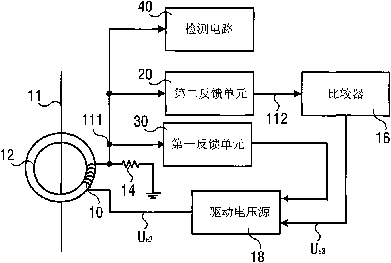
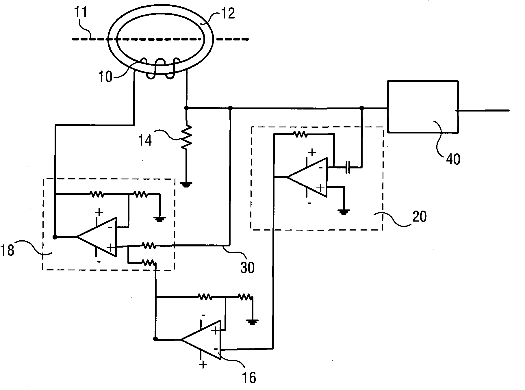
[0029] figure 2 In an exemplary embodiment of the current measuring device of the present invention, it includes a magnetic ring 12, a coil 10, a sampling resistor 14, a driving voltage source 18, a comparator 16, a first feedback unit 30 and a second feedback unit 20.

[0030] The conductor 11 that can pass the current (DC or AC) to be measured passes through the magnetic ring 12, the coil 10 is wound on the magnetic ring 12, the sampling resistor 14 is connected in series with one end of the coil 10, and the other end of the coil 10 is connected to the drive voltage source 18 The output terminal can be electrically connected, and ...


PUM


Abstract

The invention provides a current measuring device which comprises a magnetic ring, a coil, a sampling resistor, a driving voltage source, a comparator, a differentiator, a first feedback unit and a second feedback unit, wherein the first feedback unit is used for acquiring a first feedback signal on the sampling resistor; the first feedback signal can be electrically connected with one input end of the driving voltage source; the second feedback unit can be used for acquiring the first feedback signal on the sampling resistor; after the first feedback signal is subjected to differentiation processing, a second feedback signal is obtained; the second feedback signal can be electrically connected with one input end of the comparator; and an output of the comparator can be electrically connected with the other input end of the driving voltage source. Due to the adoption of the current measuring device disclosed by the invention, a reverse control point of an output voltage of the driving voltage source arranged in a nonlinear area of a BH curve (magnetization curve) of the magnetic ring can be close to a real intersection point of the nonlinear area and a linear area as far as possible, the measuring range of a current to be measured is expanded, the measuring accuracy is improved and meanwhile, the power consumption of the measuring device in the measuring process is reduced. The invention also provides a current measuring method and particularly relates to the current measurement of a direct current or an alternate current on the basis of a magnetic modulation principle.

Description

technical field [0001] The present invention relates to a current measuring device and a current measuring method thereof, in particular to a current measuring device and a current measuring method based on the principle of magnetic modulation, which are especially suitable for the measurement of Class B residual current of alternating current and / or direct current. Background technique [0002] The AC and / or DC current test method based on magnetic modulation technology has been widely used, which uses a driving voltage source to alternately set the working state of the magnetic core as figure 1 The linear and nonlinear regions of the magnetic core magnetization curve (also known as hysteresis curve, BH curve, hereinafter referred to as BH curve) are shown, and the intersection point of the linear region and the nonlinear region in the BH curve is judged (as shown by the dotted circle in the figure) is very important, which is beneficial to reverse the output voltage of the...

Claims


Application Information

Patent Timeline
IPC IPC(8): G01R19/00G01R15/18
CPCG01R19/20G01R15/185G01R33/0023G01R33/0041
Inventor 闵应宗马里奥·丹克特杜峰陈维刚卓越
Owner SIEMENS AG
Why Eureka
Try Eureka