Supercharge Your Innovation With Domain-Expert AI Agents!

Sensorless induction motor control device having function of correcting slip frequency of motor

A technology of induction motor and slip frequency, applied in four-quadrant motor control, motor generator control, AC motor control and other directions, can solve the problems of low voltage command, the motor can not output output, no flow, etc.

Active Publication Date: 2013-04-03
FANUC LTD
View PDF4 Cites 0 Cited by
  • Summary
  • Abstract
  • Description
  • Claims
  • Application Information

AI Technical Summary

Problems solved by technology

As a result, the estimated speed value ω r ^, excitation frequency command ω1 cmd Deviation from the true value causes the voltage command to be lower than the ideal value, and the motor cannot output the desired output
[0005] That is, when there is an error in the speed estimation value in the high-speed range, there is a problem that the current does not flow in the desired phase and the output drops.

Method used


Image

  • Sensorless induction motor control device having function of correcting slip frequency of motor
  • Sensorless induction motor control device having function of correcting slip frequency of motor
  • Sensorless induction motor control device having function of correcting slip frequency of motor

Examples


Embodiment Construction

[0017] Embodiments of the present invention will be described in detail below with reference to the drawings. In the drawings, the same reference numerals are given to the same components.

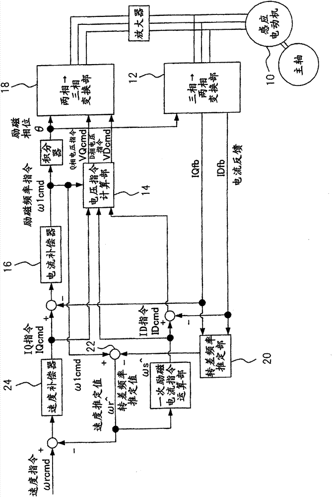
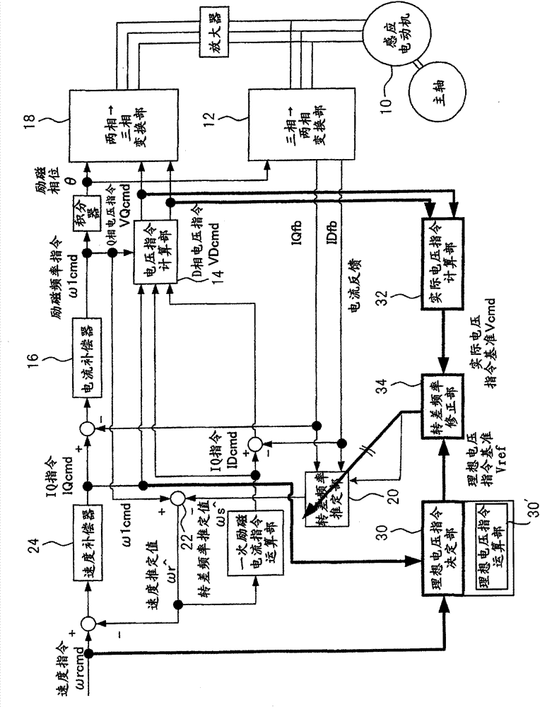
[0018] With reference to the accompanying drawings, figure 2 It is a block diagram showing a sensorless induction motor control device having a slip frequency correction function according to the first embodiment of the present invention.

[0019] In vector control, the slip frequency ω s It has the following relationship with D-phase current ID and Q-phase current IQ.

[0020] ω s = R 2 / L 2 ·IQ / ID (1)

[0021] Among them, R 2 is the secondary resistance, L 2 is the secondary reactance. Also, if the motor speed is set to ω r , then the excitation frequency ω1 is:

[0022] ω1=ω r +ω s (2)

[0023] The relationship between D-phase voltage VD and Q-phase voltage VQ and ID, IQ, ω1 is as follows:

[0024] VD=R 1 ·ID-σ·L 1 ·ω1·IQ (3)

[0025] VQ=R 1 ·IQ+L 1 ·ω1·ID (4) ...


PUM


Abstract

A sensorless induction motor control device with a function of correcting a slip frequency wherein a slip frequency estimation unit estimates the slip frequency from at least one kind of current flowing through the motor. A voltage command value calculation unit calculates a D-phase voltage command value and a Q-phase voltage command value which are used for controlling a voltage applied to the motor using a Q-phase current command value calculated based on a difference between a speed estimation value, which is calculated using an estimation value of the slip frequency, and an externally supplied speed command value. An ideal voltage command value determination unit determines an ideal voltage command value using the speed command value and the Q-phase current command value. An actual voltage command value calculation unit calculates an actual voltage command value using the D-phase voltage command value and the Q-phase voltage command value. and A slip frequency correction unit compares the ideal voltage command value with the actual voltage command value and changes the estimation value of the slip frequency to make it smaller if the actual voltage command value is smaller than the ideal voltage command value.

Description

technical field [0001] The present invention relates to a sensorless induction motor that is controlled by estimating the slip frequency from the current flowing in the coil of the motor instead of using a speed sensor to detect the speed of the motor, and estimating the speed of the motor using the slip frequency control device. Background technique [0002] Various methods are described in Japanese Patent No. 3067659 (JP3067659B), for example, regarding the control method of an induction motor without a speed sensor. However, in this control, the Slip rate is used to calculate the estimated speed and perform feedback control. When the speed feedback data is correct, the voltage command generated by this control becomes a desired command value. [0003] figure 1 It is a block diagram showing the configuration of a conventional sensorless induction motor control device that does not have a slip frequency correction function. figure 1 The control device is an independent ...

Claims


Application Information

Patent Timeline
IPC IPC(8): H02P21/14H02P21/00H02P21/18H02P21/22H02P21/24H02P23/07H02P23/14H02P23/16H02P27/04H02P27/06
CPCH02P23/14
Inventor 置田肇秋山隆洋堤智久
Owner FANUC LTD
Features
  • R&D
  • Intellectual Property
  • Life Sciences
  • Materials
  • Tech Scout
  • Unparalleled Data Quality
  • Higher Quality Content
  • 60% Fewer Hallucinations
Learn More