Induction motor controller

a technology of induction motor and controller, which is applied in the direction of motor/generator/converter stopper, dynamo-electric gear control, dynamo-electric converter control, etc., can solve the problems of deteriorating controllability or destabilizing control, requiring longer determination time, and poor controllability degradation, so as to prevent the effect of deterioration of controllability

Inactive Publication Date: 2008-07-17
HITACHI IND EQUIP SYST CO LTD
View PDF12 Cites 7 Cited by
  • Summary
  • Abstract
  • Description
  • Claims
  • Application Information

AI Technical Summary

Benefits of technology

[0012]The present invention can prevent degradation in controlla

Problems solved by technology

A deviation of the actual value of a motor parameter from the parameter set in a controller caused by this motor parameter variation may degrade the controllability or destabilize the control.
In addition, the method of the above Patent Documents 4 has a problem in that each motor parameter is not determined until all of them have been determined, thus requiring longer time for the determination.
Further, if the operating condition required for measuring motor parameters is not satisfied

Method used


Image

  • Induction motor controller
  • Induction motor controller
  • Induction motor controller

Examples


first embodiment

A First Embodiment

[0019]An induction motor controller according to a first embodiment of the invention will be described with reference to FIGS. 1, 2 and 3.

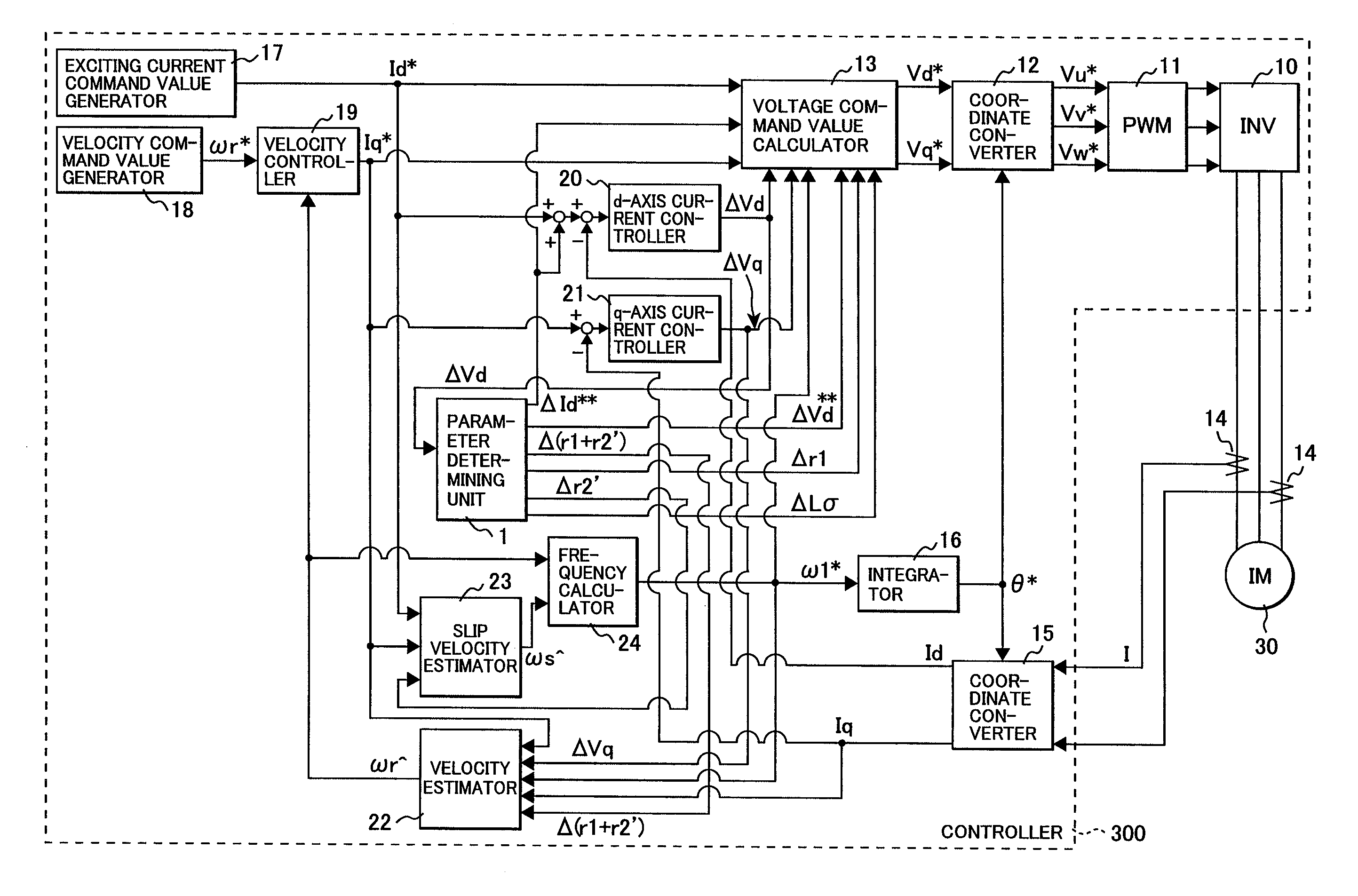
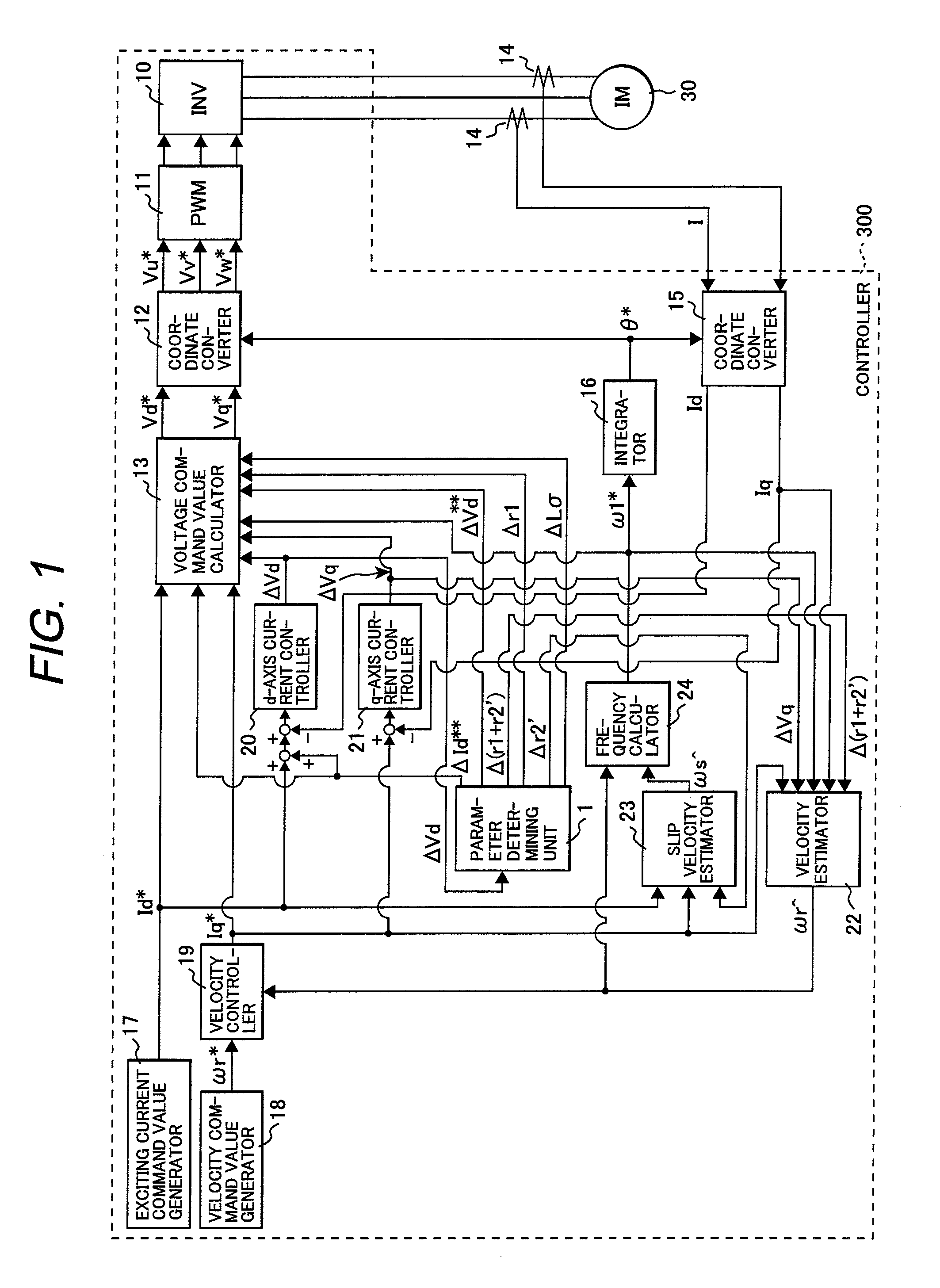
[0020]In a block diagram of FIG. 1, a three-phase induction motor 30 is connected to an induction motor controller 300 where a current detector 14 detects a current I of the induction motor 30. The current detector 14 detects currents in two of the U phase, V phase, and W phase. Here, the current in the other phase can be uniquely determined because the sum of the currents in the three phases is equal to zero.

[0021]The induction motor controller 300 controls an inverter (INV) 10 so as to drive the induction motor 30 to achieve target values of a d-axis current command value Id* generated by an exciting current command value generator 17 and a velocity command value ωr* generated by a velocity command value generator 18. The function of the inverter 10 is provided by power switching devices, while the below described functions are...

second embodiment

A Second Embodiment

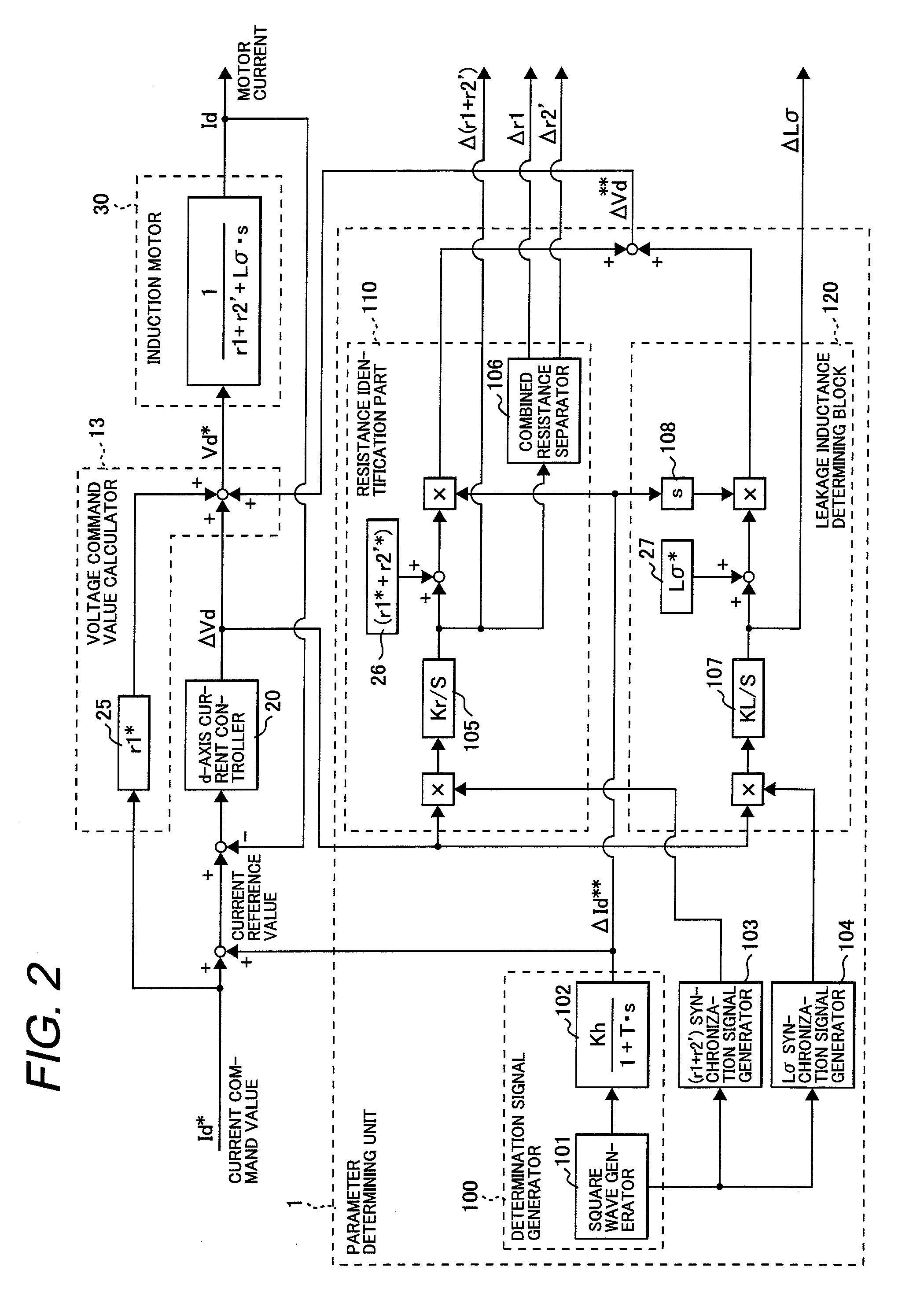
[0060]Although the first embodiment described above uses the square wave generator 101 to add the quasi-square wave signal (quasi-rectangular wave signal) to the d-axis current command value, a sinusoidal wave signal may be added.

[0061]A parameter determining unit according to a second embodiment of the invention will be described with reference to FIGS. 4 and 5. In FIG. 4, a determination signal generator 200 is configured with a sinusoidal wave generator 201, while a (r1+r2′) synchronization signal generator 203 and a Lσ synchronization signal generator 204 are different from those used in the first embodiment of FIG. 2. The other parts are identical to corresponding parts in FIG. 2, and therefore are numbered in the same manner as FIG. 2 and will not be described again here. The operating principle will first be described.

[0062]When Idh in the equation (17) is a sinusoidal wave Ids·sin ωt having an amplitude of Ids and an angular frequency of ω, the equation (1...


PUM


Abstract

The present invention provides an induction motor controller which includes: a circuit for generating a d-axis current reference signal from a d-axis current command value and a periodically varying periodic signal; a d-axis current controller for controlling a d-axis motor current flowing through an induction motor to be controlled to match the d-axis current reference signal; parameter determining means for calculating and determining a motor parameter of the induction motor based on a deviation of the d-axis motor current from the d-axis current reference signal, and controlling a voltage applied to the induction motor using a compensation voltage calculated from the calculated and determined motor parameter, in which a control parameter for controlling the induction motor is set based on the calculated and determined motor parameter.

Description

CLAIM OF PRIORITY[0001]The present application claims priority from Japanese application serial No. 2007-005578, filed on Jan. 15, 2007, the content of which is hereby incorporated by reference into this application.FIELD OF THE INVENTION[0002]The present invention relates to induction motor controllers using motor parameters.BACKGROUND OF THE INVENTION[0003]The rotating torque of an induction motor is produced by an interaction between a rotating magnetic field generated by its stator winding and an induced current flowing through its rotor winding. The rotor and stator windings are represented by a motor equivalent circuit, in which the motor parameters of primary and secondary resistances and leakage inductance determine the voltage-current characteristics of the induction motor.[0004]Methods for controlling a motor described in Patent Documents 1 to 3 use motor parameters set in a controller to control the output currents and voltages of an inverter such that the actual velocity...

Claims


Application Information

Patent Timeline
IPC IPC(8): H02P27/08H02P21/14H02P21/00H02P21/18H02P21/22H02P21/24H02P21/28H02P23/07H02P23/08H02P23/14H02P23/16H02P27/04H02P27/06
CPCH02P21/085H02P2207/01H02P21/145H02P21/09H02P21/16H02P27/04
Inventor YAMAMOTO, KOUKIOKUYAMA, TOSHIAKITOMITA, HIROYUKIIWAJI, YOSHITAKANAGATA, KOICHIRO
Owner HITACHI IND EQUIP SYST CO LTD
Why Eureka
Try Eureka