

Induction motor control
a technology of electric commutation and motor, which is applied in the direction of machines/engines, respirators, liquid fuel engines, etc., can solve the problems of reducing the output torque of the motor, reducing the availability of rare earth metals, and high motor cost, so as to reduce the pressure error
Active Publication Date: 2017-12-21
RESMED MOTOR TECH
View PDF3 Cites 7 Cited by
- Summary
- Abstract
- Description
- Claims
- Application Information
AI Technical Summary
Benefits of technology
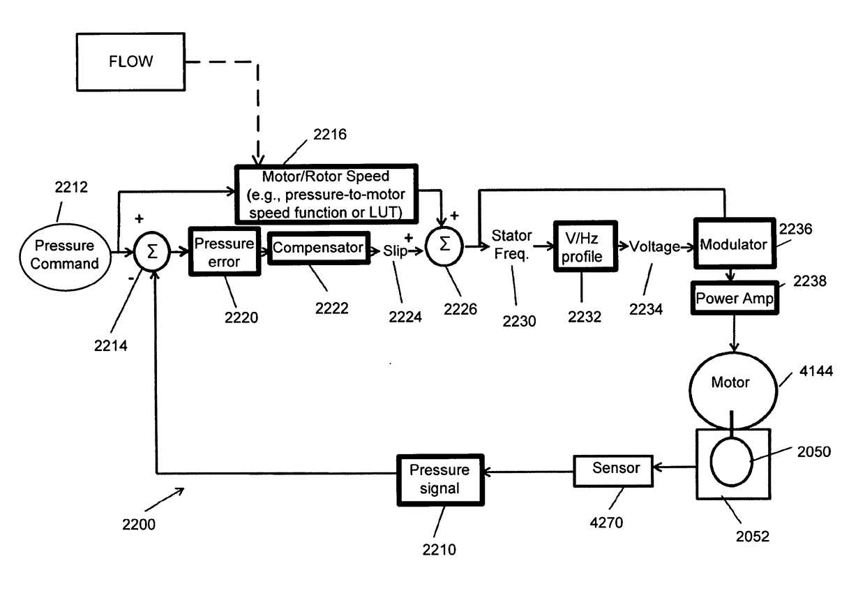
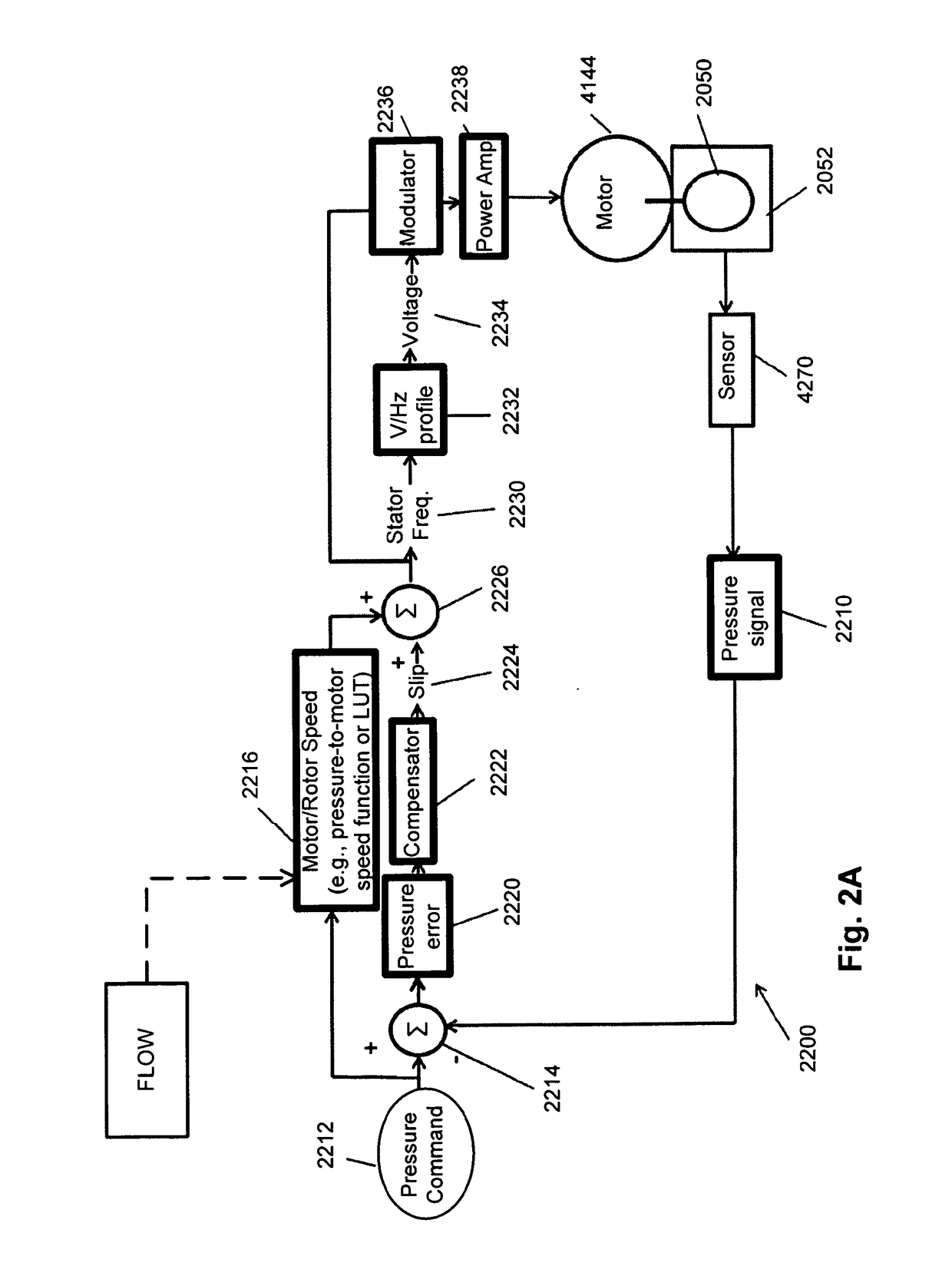
The present technology relates to controlling the speed of an induction motor in a blower. The method involves setting a desired pressure level for the fluid supply, determining a desired rotor speed based on this level, inducing rotation of the rotor by providing excitation to the stator, measuring the pressure of the fluid, comparing the measured pressure to the set pressure to determine a pressure error, and adjusting the slip frequency to minimize the pressure error and adjust the rotor speed of the blower. The technical effect is to ensure a stable supply of pressurized fluid at a desired pressure level through an efficient and effective control method for the speed of the induction motor in a blower.
Problems solved by technology
However, such permanent magnets are expensive resulting in a higher cost motor.
Furthermore the availability of these rare earth metals is limited.
Therefore increasing the frequency without increasing the voltage will cause a reduction of the flux in the magnetic circuit thus reducing the motor's output torque.
The reduced motor torque will tend to increase the slip with respect to the new supply frequency.
This in turn causes a greater current to flow in the stator, increasing the IR (current (I)*resistance (R)) voltage drop across the windings as well as the I2R power losses in the windings.
The result is a major drop in the motor efficiency.
Increasing the frequency still further will ultimately cause the motor to stall.
However, variable speed induction motors are available but require a motor controller that provides a variable frequency and voltage output and this increases the size and cost of the motor drive.
Induction motors have been used in a range of heavy industry applications, machine tools and domestic appliances such as washing machines, pumps, lifts, cranes, large capacity exhaust fans and mills Generally induction motors are relatively large and are rarely used in small power ranges and high speed devices especially medical devices due to lower efficiency and manufacturing challenges.
Induction motors generally have not been used in such RPT devices due to their generally larger size and the cost of control.
In particular for medical devices that may be used for long periods of time, such as throughout the day, and / or during sleep, such as PAP devices and / or ventilators the level of noise emitted is a significant issue.
For other forms of therapy, such as the delivery of oxygen, the patient interface may not include a seal sufficient to facilitate delivery to the airways of a supply of gas at a positive pressure of about 10 cmH2O.
Delivery of a flow of air without humidification may cause drying of airways.
A range of artificial humidification devices and systems are known, however they may not fulfil the specialised requirements of a medical humidifier.
Room-based systems (e.g. a sauna, an air conditioner, or an evaporative cooler), for example, may also humidify air that is inspired by the patient, however those systems would also humidify and / or heat the entire room, which may cause discomfort to the occupants.
Furthermore medical humidifiers may have more stringent safety constraints than industrial humidifiers
Method used
View moreImage
Smart ImageViewing Examples

Examples
example 1
[0231]A control system for an induction motor configured to adjust a slip frequency of the induction motor based on a measured characteristic of a flow of fluid produced by a rotating rotor of the induction motor.
example 2
[0232]The control system of EXAMPLE 1, wherein an impeller is attached to the rotating rotor and configured to rotate with the rotor to produce the flow of fluid.
example 3
[0233]The control system of any one of EXAMPLEs 1-2, wherein a rotor speed is predetermined based on a set level of the characteristic of the flow of fluid to be produced by the rotating rotor.
Login to View More PUM
 Abstract
A method of a control system (2200) controls an inductance motor in a blower including an impeller and volute using a pressure compensation control system. The control system may be implemented in a respiratory pressure therapy device. The control system may include a sensor configured to provide a pressure signal indicative of the pressure of a flow of fluid produced by the blower. A measured pressure may be compared to a set pressure to determine a pressure error. A slip frequency may be adjusted as a function of the pressure error in an attempt to eliminate or minimise the pressure error.
Description
1 CROSS-REFERENCE TO RELATED APPLICATIONS[0001]This application claims the benefit of the filing date of U.S. Provisional Patent Application No. 62 / 052,020 filed Sep. 18, 2014, and U.S. Provisional Patent Application No. 62 / 135,880, filed on Mar. 20, 2015, the disclosures of which are hereby incorporated herein by reference.2 BACKGROUND OF THE INVENTION2.1 Field of the Invention[0002]The present technology relates to electronically commutated motors, particularly Alternating Current (AC) induction motors, and the use thereof. These types of electronically commutated motors produce continuous rotational torque without the use of permanent magnets. The present technology further relates to a control algorithm for a blower comprising an induction motor. In some aspects the motors may be used in medical devices or apparatus configured to treat, prevent and / or ameliorate respiratory-related disorders.2.2 Description of the Related Art2.2.1 Electrical Motors[0003]One of the subgroups of e...
Claims
Login to View More Application Information
Patent Timeline
 Patent Type & AuthorityApplications(United States)
IPC IPC(8): F04D27/00A61M16/00F04D25/06A61M16/10A61M16/16H02P27/04F04D29/28F04D17/16
CPCF04D27/004A61M2205/583F04D29/281H02P27/045H02P27/047A61M16/0069A61M16/024A61M16/107A61M16/161A61M16/0003A61M16/0051F04D17/16A61M2016/0027A61M2016/0039A61M2205/3368A61M2205/42A61M2205/581A61M2205/582F04D25/06A61M16/16A61M2205/502F05D2270/301H02P2207/01H02P6/34A61M16/026Y02B30/70A61M16/0066H02P23/08A61M16/10
InventorFLEMING, DAVID JAMESGRUNBERG, MICHAELNAGORNY, ALEKSANDR S.SADEGHI, SIAVASH
OwnerRESMED MOTOR TECH