Control circuit and control method for light emitting diode (LED) driver

A LED driver and control circuit technology, applied in the electronic field, can solve the problems of reduced current transmission ratio, adverse effects on circuit stability and service life, space on a large board, etc., achieve stability and increase service life, and enhance circuit design efficiency , the effect of reducing the number of devices

Active Publication Date: 2012-02-01
SILERGY SEMICON TECH (HANGZHOU) CO LTD
View PDF3 Cites 31 Cited by
  • Summary
  • Abstract
  • Description
  • Claims
  • Application Information

AI Technical Summary

Problems solved by technology

[0005] (1) For long-life power supply applications, due to the aging of the optocoupler over time, the current transmission ratio gradually decreases, which has an adverse effect on the stability and service life of the circuit;
[0006] (2) Moreover, in such an implementation, the number of components is large, which means that larger board space, higher cost, and lower reliability are required;
[0007] (3) The added induction detection circuit additionally increases the power consumption of the circuit and reduces the efficiency of the constant current regulation power supply;
[0008] (4) For today's applications, the efficiency and energy saving requirements of LED drivers are becoming more and more important, and LED applications also require smaller sizes, so the traditional circuits that sample the above implementation methods can no longer meet the relevant requirements

Method used


Image

  • Control circuit and control method for light emitting diode (LED) driver
  • Control circuit and control method for light emitting diode (LED) driver
  • Control circuit and control method for light emitting diode (LED) driver

Examples


Embodiment Construction

[0071] Preferred embodiments of the present invention will be described in detail below with reference to the accompanying drawings, but the present invention is not limited to these embodiments. The present invention covers any alternatives, modifications, equivalent methods and schemes made on the spirit and scope of the present invention. In order to provide the public with a thorough understanding of the present invention, specific details are set forth in the following preferred embodiments of the present invention, but those skilled in the art can fully understand the present invention without the description of these details.

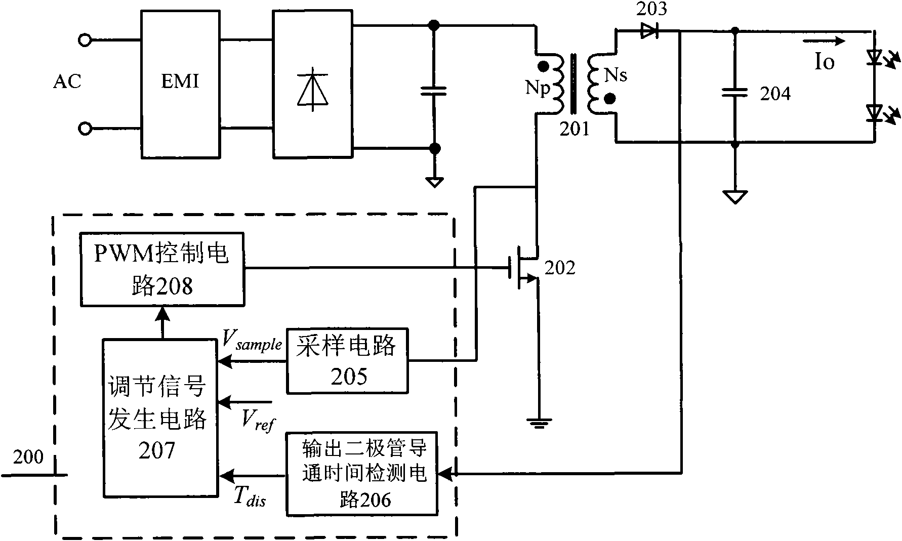
[0072] refer to figure 2 , shows a functional block diagram of an embodiment of a control circuit of an LED driver according to the present invention, wherein the LED driver adopts a flyback topology, which includes the following parts:

[0073] On the primary side of the transformer 201, the external AC input is sequentially input to the prima...


PUM


Abstract

The invention relates to a control method for a control circuit of a light emitting diode (LED) driver. The LED driver has a flyback topological structure; the control circuit is positioned on a primary side of a transformer and comprises a sampling circuit, a conduction time detection circuit of an output diode on a secondary side of the transformer, a regulation signal generation circuit and a pulse width modulation (PWM) control circuit, wherein the sampling circuit is used for acquiring a sampling signal for representing an output signal of the LED driver on the primary side of the transformer; the conduction time detection circuit is used for detecting conduction time of the diode; the regulation signal generation circuit is used for regulating conduction time of the sampling signal,a reference source and the output diode on the secondary side of the transformer and generating a regulation signal; and the PWM control circuit is used for receiving the regulation signal and generating a control signal to control the turning on and turning off of a switching device in the LED driver, so stable output of the LED driver is retained.

Description

technical field [0001] The invention relates to the field of electronic technology, in particular to a control circuit of an LED driver and a control method thereof. Background technique [0002] With the continuous innovation and rapid development of the lighting industry, coupled with the increasing importance of energy saving and environmental protection, LED lighting, as a revolutionary energy-saving lighting technology, is developing rapidly. However, since the brightness of an LED lamp is related to the light output intensity parameter, it is directly proportional to its current and forward voltage drop, and changes with temperature. Therefore, LEDs need an additional circuit to generate a constant current to drive them. Such as figure 1 As shown, it is a functional block diagram of a traditional off-line constant current driver for LEDs, which is realized by an isolated flyback converter with an output current regulation circuit. The main structure of the LED drivi...

Claims


Application Information

Patent Timeline
IPC IPC(8): H05B37/02H02M3/335H05B44/00
CPCH05B33/0887H02M3/33523H05B33/0815Y02B20/346Y02B20/30H05B45/385
Inventor 陈圣伦
Owner SILERGY SEMICON TECH (HANGZHOU) CO LTD
Why Eureka
Try Eureka