Side airbag device for vehicle

An airbag device and airbag technology are applied in the directions of vehicle safety arrangement, pedestrian/occupant safety arrangement, vehicle components, etc., which can solve the problem of difficulty in ensuring the thickness of the airbag, and achieve the effect of simple structure and easy production.

Inactive Publication Date: 2012-02-01
TOYOTA JIDOSHA KK
View PDF1 Cites 10 Cited by
  • Summary
  • Abstract
  • Description
  • Claims
  • Application Information

AI Technical Summary

Problems solved by technology

Moreover, in order to restrict the passage of gas between the upper chamber and the lower chamber around the check valve, it is necessary to seal the side edge of the airbag front side of the check valve with a suture line or the like that divides the upper chamber and the lower chamber. Sewing makes it difficult to ensure the airbag thickness of the airbag on the partition area of ​​the upper and lower chambers

Method used


Image

  • Side airbag device for vehicle
  • Side airbag device for vehicle
  • Side airbag device for vehicle

Examples


no. 1 Embodiment approach

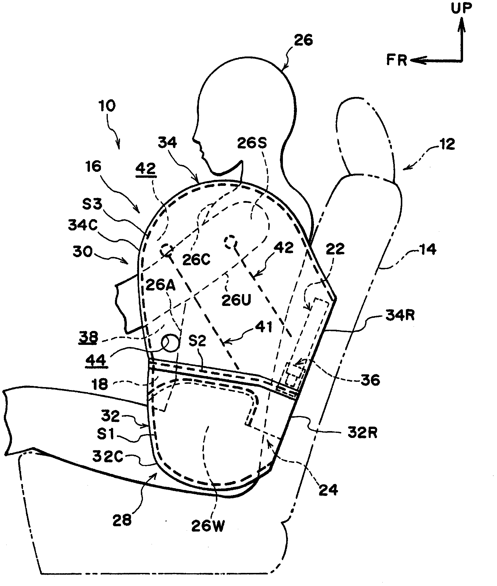
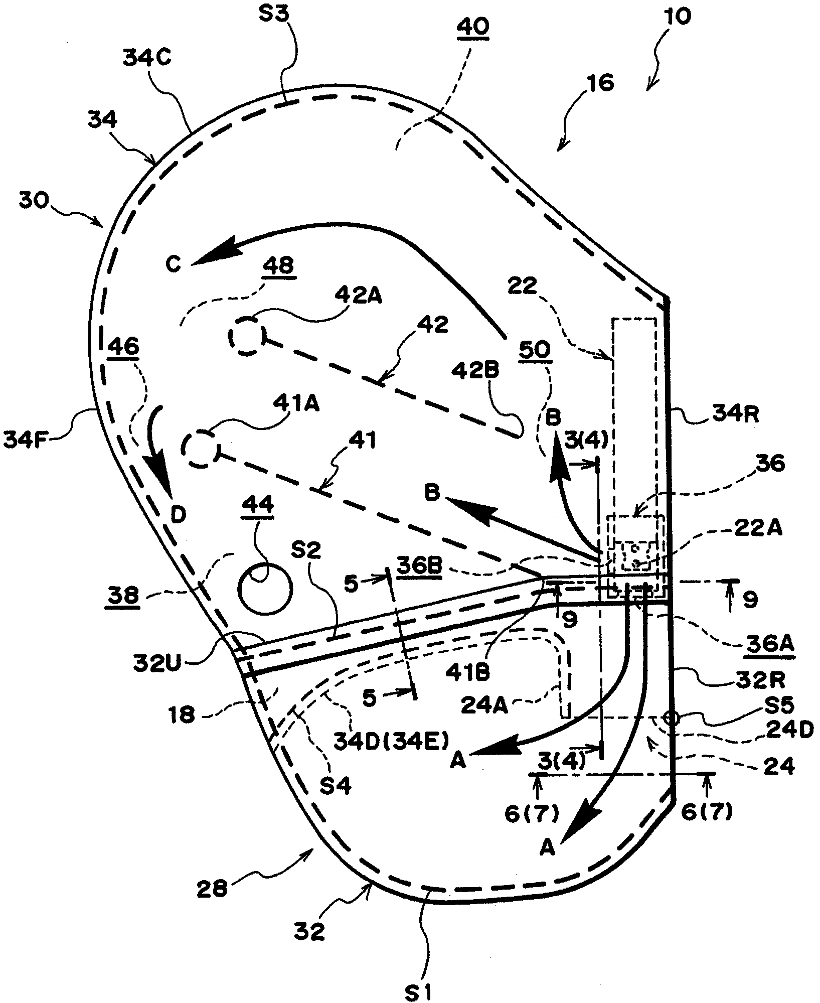
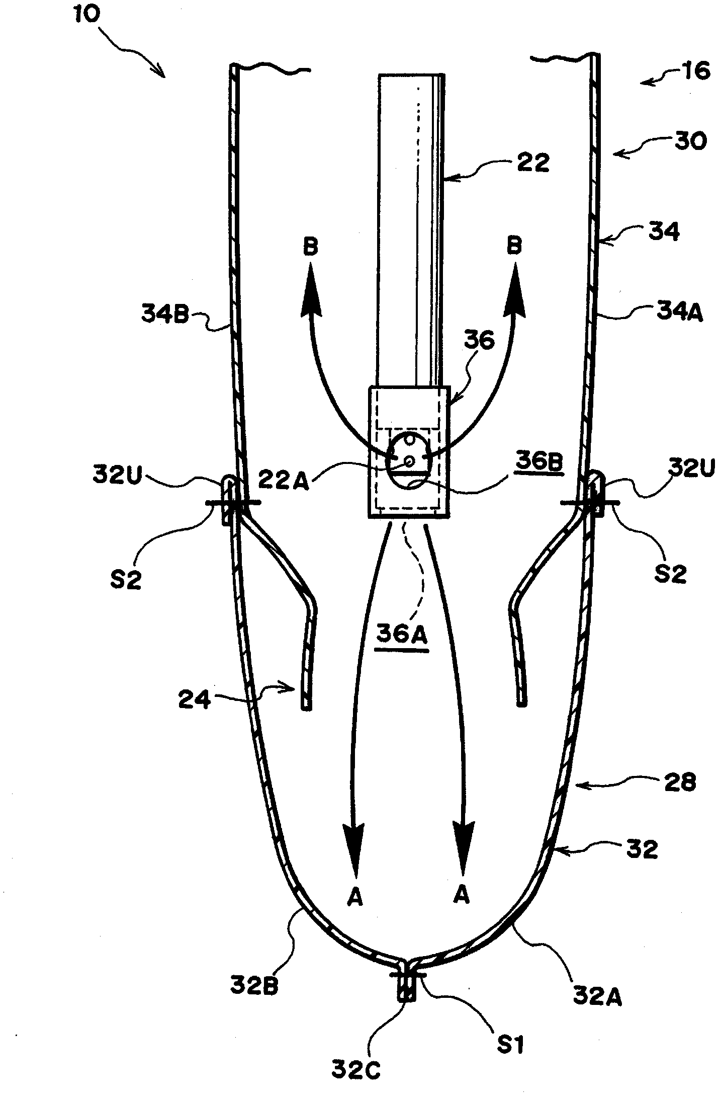
[0113] exist Figure 1 to Figure 3 Among them, the side airbag device 10 for a vehicle in this embodiment relates to a side airbag device mounted, for example, on the side of the seat back 14 of the seat 12 for a vehicle, and the side airbag device 10 for a vehicle has a side airbag. Air bag 16 , partition wall 18 , inflator 22 and check valve 24 .

[0114] The side airbag 16 is configured to receive gas supplied from the inflator 22 in the event of a side collision, and to inflate and expand on the side of the occupant 26 seated on the vehicle seat 12 . The lower chamber 28 , which is an example of a high-pressure chamber, becomes a high-pressure side during expansion and deployment, and the upper chamber 30 , an example of a low-pressure chamber, which is a lower pressure than the high-pressure chamber. The side airbag 16 is configured such that the lower chamber 28 and the upper chamber 30 are each inflated and deployed when a side collision occurs.

[0115] The lower cha...

no. 2 Embodiment approach

[0172] refer to Figure 18 , in the vehicle side airbag device 20 according to the present embodiment, in the side airbag 16 in the inflated and deployed state, the check valve 24 is formed by the rear end portion 18R of the partition wall 18 and the rear side of the side airbag 16 . The surface 16R is formed, and is configured such that the flow path of the gas is opened by separating the rear end portion 18R of the partition wall 18 from the rear inner surface 16R; The flow path of the gas is closed.

[0173] This embodiment is formed, for example, by folding one base fabric 60 in two toward the seat front side with the seat rear end 60R as the center, and Figure 19 As shown, the outer base fabric 60A located outside in the seat width direction and the inner base fabric 60B located inside in the seat width direction are sewn at the peripheral edge portion 60C (sewn portion S6 ). The partition wall 18 is constituted as a separate part from the side airbag 16, and is sewn t...


PUM


Abstract

A side airbag device for a vehicle has a simple structure which allows a high-pressure chamber of a side airbag to be promptly inflated and expanded and allows the pressure in the high-pressure chamber to be maintained for a long time. A side airbag (16) has a high-pressure chamber (28) and a low-pressure chamber (30) the inner pressure of which becomes a pressure lower than the pressure in the high-pressure chamber (28). An inflator (22) is provided in the low-pressure chamber (30) with a gas discharge section (22A) facing the high-pressure chamber (28). In a side collision, gas from the inflator (22) is supplied mainly toward the high-pressure chamber (28) and is supplied also to the low-pressure chamber (30). The high-pressure chamber (28) and the low-pressure chamber (30) are partitioned by a partition wall (18). A check valve (24) mounted to the partition wall (18) is opened by the pressure of the gas supplied from the inflator (22), which is provided in the low-pressure chamber (30), toward the high-pressure chamber (28), and thus the check valve (24) permits the gas to flow from the low-pressure chamber (30) to the high-pressure chamber (28). When the inflator (22) completes the discharge of the gas, the gas tries to flow back from the high-pressure chamber (28) to the low-pressure chamber (30), but the check valve (24) restricts such flow of the gas.

Description

technical field [0001] The present invention relates to a side airbag device for a vehicle. Background technique [0002] There is currently disclosed a structure in which the inside of the airbag for side impact is divided into an upper chamber and a lower chamber by a seam line, and a pair of upper and lower chambers is formed between the seam line and the rear edge of the airbag. The communication part between the chamber and the lower chamber is provided with a cylindrical one-way valve on the communication part, and the gas generator is arranged in the one-way valve, and the flow from the lower chamber to the upper chamber is prevented by using the one-way valve. The gas flows out so that even if the occupant's body hits the lower chamber, the air pressure in the lower chamber can be maintained in a high state (refer to Patent Document 1). [0003] Patent Document 1: Japanese Patent Laid-Open No. 2004-256017 [0004] However, since in the above-mentioned conventional ...

Claims


Application Information

Patent Timeline
Patent Type & Authority Applications(China)
IPC IPC(8): B60R21/231B60R21/233B60R21/239B60R21/26B60R21/261
CPCB60R21/261B60R2021/23146B60R21/26B60R21/239B60R21/2171B60R21/233B60R2021/23324B60R21/23138
Inventor 山本一人
Owner TOYOTA JIDOSHA KK
Why Eureka
Try Eureka