
Oil-fume separator based on diversion at 360 degrees

An oil fume separator and high-level technology, which is applied in the field of 360-degree diversion oil fume separators, can solve the problems of affecting the suction effect of a range hood, a small collision probability between oil molecules and a separation plate, and irregular airflow passages.

Inactive Publication Date: 2012-02-08
四川开力厨具有限公司
View PDF4 Cites 8 Cited by
  • Summary
  • Abstract
  • Description
  • Claims
  • Application Information

AI Technical Summary

Problems solved by technology

This kind of filtering device is obviously much better than the oil fume filtering effect of the above two methods, but there are still the following problems: first, the channel structure is too simple, when the oil fume passes through the channel formed by the openings of the front and rear plates, the oil molecules collide with the separation plate The probability is small, so the filtering effect is not ideal; the second is that due to the irregular airflow channel, the airflow in different directions will collide and interfere with each other after entering the channel, forming a turbulent airflow, resulting in increased wind resistance, affecting the suction effect of the range hood, and the noise will also be caused by thus increased

Method used


Image

  • Oil-fume separator based on diversion at 360 degrees
  • Oil-fume separator based on diversion at 360 degrees
  • Oil-fume separator based on diversion at 360 degrees

Examples


Embodiment 1

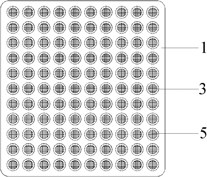
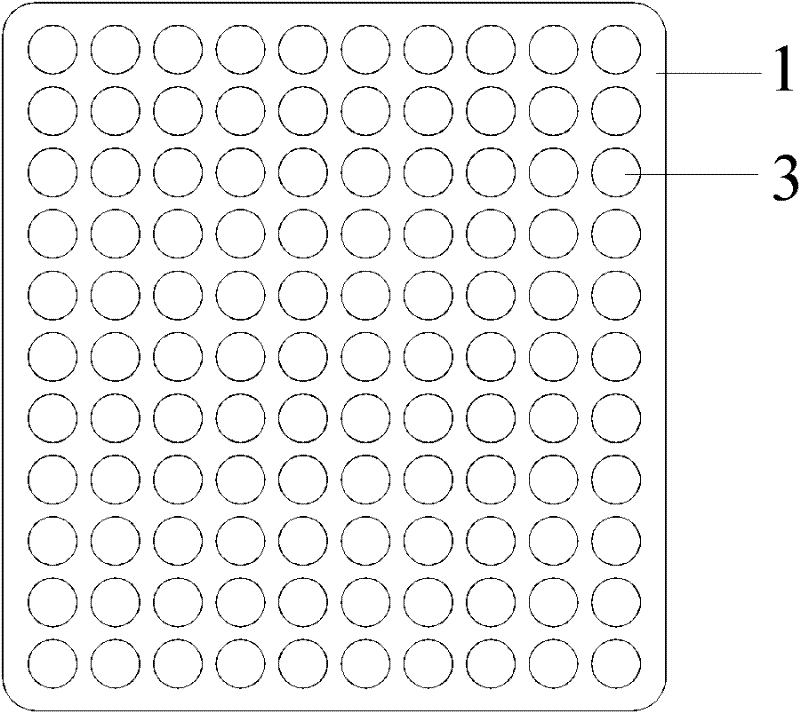
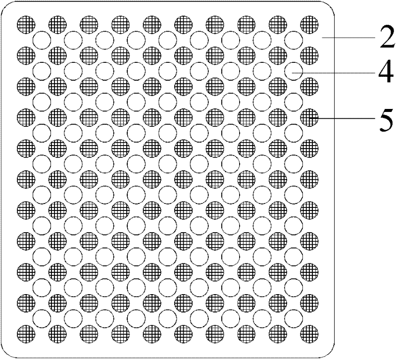
[0032] See Figure 1-Figure 4 , figure 1 It is a top view structure diagram of the 360-degree direction guide oil fume separator in embodiment 1; figure 2 It is a schematic structural view of the front plate of the 360-degree direction oil fume separator in embodiment 1; image 3 It is a schematic structural view of the back plate of the 360-degree direction oil fume separator in embodiment 1; Figure 4 It is a schematic cross-sectional structure diagram of the 360-degree direction guide oil fume separator in Example 1.

[0033] The 360-degree direction guide oil fume separator provided in this embodiment is composed of a front plate 1 and a rear plate 2, wherein a certain distance is set between the front plate 1 and the rear plate 2, and the front plate 1 is provided with an air intake The openings 3 are all circular and arranged alternately, and the edge of the air inlet 3 is set with a flange 6 of a certain height; the rear plate 2 is provided with an air outlet 4, whi...

Embodiment 2

[0037] See Figure 5 , which is a top view structural diagram of the 360-degree direction guide oil fume separator in Example 2.

[0038] In the 360-degree direction diversion oil fume separator provided in this embodiment, the air intake holes 3 of the front plate 1 are set as hexagonal holes, and the air intake holes 3 are arranged in parallel and alternate rows, and alternately arranged in columns. The air intake holes 3 of the front plate are honeycomb-shaped, and can also be arranged in parallel. The protrusion 5 corresponding to the air intake hole of the front plate on the rear plate 2 can be set as a hexagonal column, or as a spherical protrusion, and the oil filtering channel and oil fume separation effect will not change.

Embodiment 3

[0040] See Image 6 , which is a top structural schematic diagram of the 360-degree direction guide oil fume separator in Example 3.

[0041] In the 360-degree direction guide oil fume separator provided in this embodiment, the air intake holes 3 of the front plate 1 are arranged in a long strip shape and arranged in parallel with each other, and the protrusions 5 on the rear plate 2 corresponding to the air intake holes of the front plate can be set as The same shape of the elongated column, the oil filter channel and oil fume separation effect will not change.


PUM


Abstract

The invention discloses an oil-fume separator based on diversion at 360 degrees. The oil-fume separator comprises a front plate and a rear plate which are spaced from each other, wherein, the front plate is equipped with fume inlets, the rear plate is equipped with fume outlets, and the fume inlets and the fume outlets are alternately staggered with each other; and bulges are arranged among the fume outlets of the rear plate and are opposite to the fume inlets of the front plate, and clearance is arranged between the bulges and the fume inlets. Compared with the prior art, The oil-fume separator based on diversion at 360 degrees provided by the invention has the advantages of more smooth gas flow channel, small wind resistance and noise and better oil-fume separation effect.

Description

technical field [0001] The invention relates to a range hood, specifically a 360-degree direction guide oil fume separator for a range hood capable of separating oil and gas from kitchen fumes. Background technique [0002] At present, there are various types of oil fume filtering devices used in range hoods, with different shapes and structures. However, one or more layers of dense filter screens interwoven with filaments, or simple single-layer orifice plate or multi-layer orifice plate filtration methods are still generally used. According to the principle of physical separation of oil fume, the separation of oil fume must meet the following conditions: [0003] 1. The oil fume passes through the oil fume separation device at high speed under the action of suction generated by the exhaust device of the range hood; [0004] 2. The channel through which the oil fume passes through the separation device should be a curved channel in the shape of "S" or other shapes, so tha...

Claims


Application Information

Patent Timeline
IPC IPC(8): B01D45/06
Inventor 王强李平赵济田赵云峰
Owner 四川开力厨具有限公司
Learn More