Intelligent control device for automobile brake lamp

A technology of automobile braking and intelligent control, applied in signal devices, vehicle parts, transportation and packaging, etc., can solve problems such as functional limitations, rear-end collision accidents, and unscientific problems, so as to improve driving safety, reduce rear-end collision accidents, improve The effect of traffic safety

Inactive Publication Date: 2012-02-08
BEIJING INSTITUTE OF TECHNOLOGYGY
View PDF5 Cites 9 Cited by
  • Summary
  • Abstract
  • Description
  • Claims
  • Application Information

AI Technical Summary

Problems solved by technology

[0002] At present, the traditional car brake light control device is to light the brake light after the driver steps on the brake pedal to warn the rear car that the front car is braking. The problem is that when the driver of the rear vehicle sees the front When the brake light of the vehicle is on, the driver of the vehicle in front has already applied the brakes, and the vehicle in front is already in a deceleration state
This brake light control device uses the accelerator pedal switch to judge whether the driver has stepped on the accelerator pedal. If the driver has not stepped on the accelerator pedal, it is considered that the driver has the intention to brake, so that some or all of the brake light bulbs are turned on. but low brightness
However, it is unscientific for this device to simply judge the behavior of "the accelerator pedal is not pressed" as a braking intention, because in the actual driving process, it often happens that the driver does not continue to step on the accelerator pedal after releasing it. The condition of the brake pedal, that i

Method used


Image

  • Intelligent control device for automobile brake lamp
  • Intelligent control device for automobile brake lamp
  • Intelligent control device for automobile brake lamp

Examples


Embodiment Construction

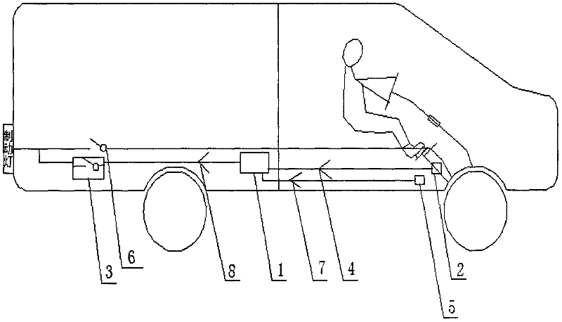
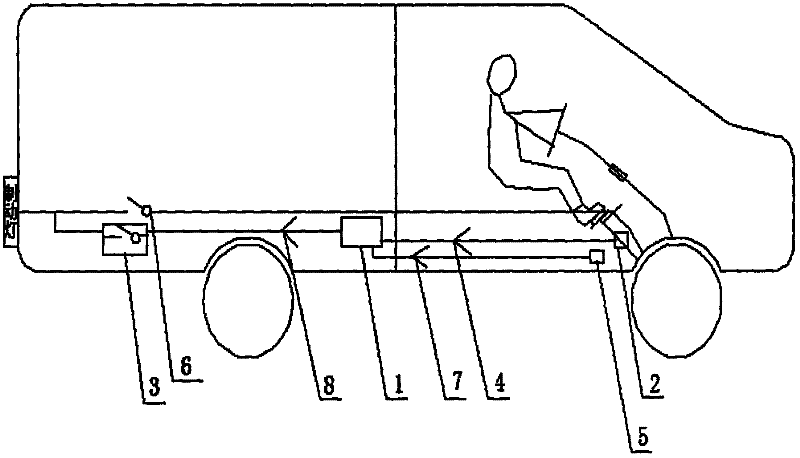
[0020] figure 1 A preferred embodiment of the invention is shown.

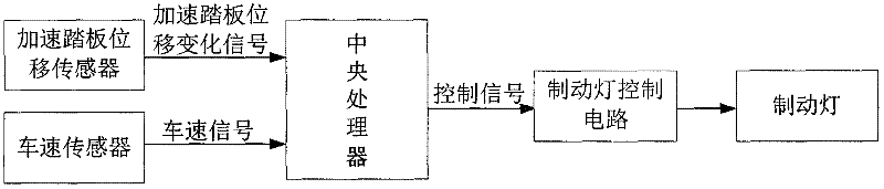
[0021] Such as figure 1 As shown, the automobile brake light intelligent control device of the present invention comprises a central processing unit 1, an accelerator pedal displacement sensor 2, a brake light control circuit 3 and a vehicle speed sensor 5; the brake light control circuit 3 and the original brake light control circuit The circuit 6 is connected in parallel; the accelerator pedal displacement sensor 2 collects the accelerator pedal displacement change signal 4 and sends it to the central processing unit 1; the central processing unit 1 calculates the acceleration pedal displacement change rate according to the accelerator pedal displacement change signal 4, and the accelerator pedal The rate of change of displacement can be divided into positive and negative points, which represent respectively stepping on the accelerator pedal and loosening the accelerator pedal; the central processing unit 1...


PUM


Abstract

The invention discloses an intelligent control device for an automobile brake lamp, which is used for preventing rear collision. The intelligent control device is characterized by comprising a central processor (1), an acceleration pedal displacement sensor (2) and a brake lamp control circuit (3), wherein the acceleration pedal displacement sensor (2) is used for acquiring an acceleration pedal displacement change signal (4) and transmitting the signal to the central processor (1); the central processor (1) is used for computing an acceleration pedal displacement change rate according to the acceleration pedal displacement change signal (4); positive and negative acceleration pedal displacement change rates represent treading of an acceleration pedal and loosening of the acceleration pedal respectively; and when the acceleration pedal displacement change rate reaches an acceleration pedal displacement change rate threshold value set in the central processor (1), i.e., the acceleration pedal releasing action of a driver is very quick, the central processor (1) considers that the driver is going to perform emergency braking and transmits a control signal (8) to the brake lamp control circuit (3), so that the brake lamp is lightened before the driver treads on a brake pedal.

Description

technical field [0001] The invention relates to the field of automobile active safety, and more particularly relates to an intelligent control device for brake lights of automobiles for preventing rear-end collisions of rear vehicles. Background technique [0002] At present, the traditional car brake light control device is to light the brake light after the driver steps on the brake pedal to warn the rear car that the front car is braking. The problem is that when the driver of the rear vehicle sees the front When the brake light of the vehicle is on, the driver of the vehicle in front has already applied the brakes, and the vehicle in front is already decelerating. The driver of the rear vehicle perceives the deceleration intention of the driver of the vehicle in front according to the lighted brake lights, and makes a deceleration decision. After depressing the brake pedal to perform the braking action, the speed of the vehicle behind begins to decrease. Because there i...

Claims


Application Information

Patent Timeline
IPC IPC(8): B60Q1/44
Inventor 吴绍斌王学伟耿若楠高利孙洪武
Owner BEIJING INSTITUTE OF TECHNOLOGYGY
Why Eureka
Try Eureka