Automatic pressing pump test device

A test device and automatic technology, which is applied in pump testing, machine/engine, liquid displacement machinery, etc., can solve the problems of damage to the surface quality of the paint, great influence on the sealing reliability of joints, and high labor intensity, etc., to achieve sealing pressure Appropriate and reliable tightening force, low labor intensity and high sealing safety

Active Publication Date: 2013-07-10
上海中航泵业股份有限公司
View PDF6 Cites 0 Cited by
  • Summary
  • Abstract
  • Description
  • Claims
  • Application Information

AI Technical Summary

Problems solved by technology

[0004] Disadvantages: high labor intensity, long time consumption, and low test efficiency; the compaction force and compaction uniformity are not easy to control, and the sealing reliability of the joint is greatly affected by human beings; the installation will destroy the quality of the painted surface to a certain extent
[0007] Disadvantages: It requires a certain amount of labor intensity; the pressing force is not easy to control, the reliability of the continuous holding of the pressing force is poor, the reliability of the sealing of the joint is poor, and the test medium is often sprayed outward, and someone needs to take care of it and pay attention to the sealing situation at all times
[0010] Disadvantages: The clamping force needs to be adjusted by the hydraulic pressure (or pneumatic pressure), which is generally not adjustable or cumbersome to adjust, and the clamping force will be too large or insufficient during the test; equipment (additional hydraulic or pneumatic equipment) has a large investment and costs High; during the test, there is additional energy consumption

Method used


Image

  • Automatic pressing pump test device
  • Automatic pressing pump test device
  • Automatic pressing pump test device

Examples


Embodiment Construction

The present invention will be further described below in conjunction with the accompanying drawings of the description.

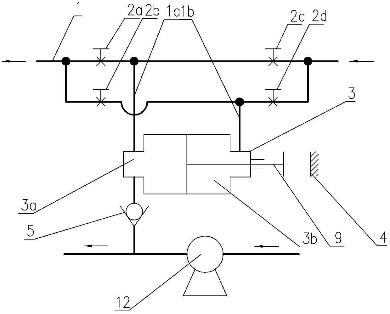
Automatic compression pump test device of the present invention, such as figure 1 As shown, it has a mounting seat 6, on which the suction pipe part and the discharge pipe part are installed, and a placement platform 6a is left between the suction pipe part and the discharge pipe part (it is better to set the placement platform 6a so that it can be adjusted up and down) for Place the tested pump 12; the suction pipe parts include the suction flange pipe 14 fixed on the mounting base 6 and the suction sealing disc 13 assembled on one end of the suction flange pipe 14 (the connection between the suction flange pipe 14 and the suction sealing disc 13 is detachable form, shown as a threaded connection);

The discharge pipe parts include a cylinder block 8 with an axial through hole fixed on the mounting seat 6, an axial channel 9a (the diameter of the axial chan...


PUM


Abstract

The invention discloses an automatic pressing pump test device. The traditional test device has low efficiency and high cost. An installation base of the automatic pressing pump test device is used for installing and fixing a suction pipe part and an exhaust pipe part, and providing a placement platform for a tested pump; the tested pump is positioned between the suction pipe part and the exhaustpipe part which are used as pipeline channels of a test medium and also used as pressing members of the tested pump; a piston of the exhaust pipe part can be flexed within a certain range when the pressure of a cylinder cavity changes so as to realize pre-pressing, working pressing and concession of the tested pump; and the working pressing of the piston to the tested pump is automatically realized by the pressure of an exhaust hole of the tested pump. In the whole test process, the pump is placed on the corresponding position and centered, the connection and the separation of the pump and a test pipeline system can be completed rapidly; meanwhile, because the pressing force of the working pressing is from the tested pump, additional energy sources can not be provided, thus the energy is saved and the environment is protected.

Description

technical field [0001] The invention relates to an automatic compaction pump test device, in particular to a pump test device for delivery test, which is used for the test of pumps (such as pipeline pumps and vertical multistage centrifugal pumps) with symmetrically arranged inlet and outlet. Background technique [0002] Pump test is an essential and important link in the pump production process. During the test, it takes a lot of time and energy to put the pump into the test stand and remove the pump from the test stand, resulting in a decrease in the efficiency of the pump test and an increase in cost. When conducting pump tests, there are generally three installation methods as follows: [0003] 1. Flange connection installation: the pump inlet and outlet and the test pipeline system are connected by flanges and bolts. This is the more common method at present. [0004] Disadvantages: high labor intensity, long time consumption, low test efficiency; the compaction for...

Claims


Application Information

Patent Timeline
Patent Type & Authority Patents(China)
IPC IPC(8): F04B51/00
Inventor 徐松樟
Owner 上海中航泵业股份有限公司
Why Eureka
Try Eureka